Tilt Trigger Drive Circuits and Electronics

A technology for driving circuits and electronic products, applied in the field of circuits, which can solve problems such as shortening service life

Active Publication Date: 2020-06-26
AEROSPACE INFORMATION
View PDF6 Cites 0 Cited by
  • Summary
  • Abstract
  • Description
  • Claims
  • Application Information

AI Technical Summary

Problems solved by technology

[0004] The purpose of the present disclosure is to provide a tilt trigger drive circuit and electronic products, which are used to solve the technical problem of shortened service life caused by frequent opening and closing of electronic products in the related art

Method used


Image

  • Tilt Trigger Drive Circuits and Electronics
  • Tilt Trigger Drive Circuits and Electronics

Examples


Embodiment Construction

[0046] Specific embodiments of the present disclosure will be described in detail below in conjunction with the accompanying drawings. It should be understood that the specific embodiments described here are only used to illustrate and explain the present disclosure, and are not intended to limit the present disclosure.

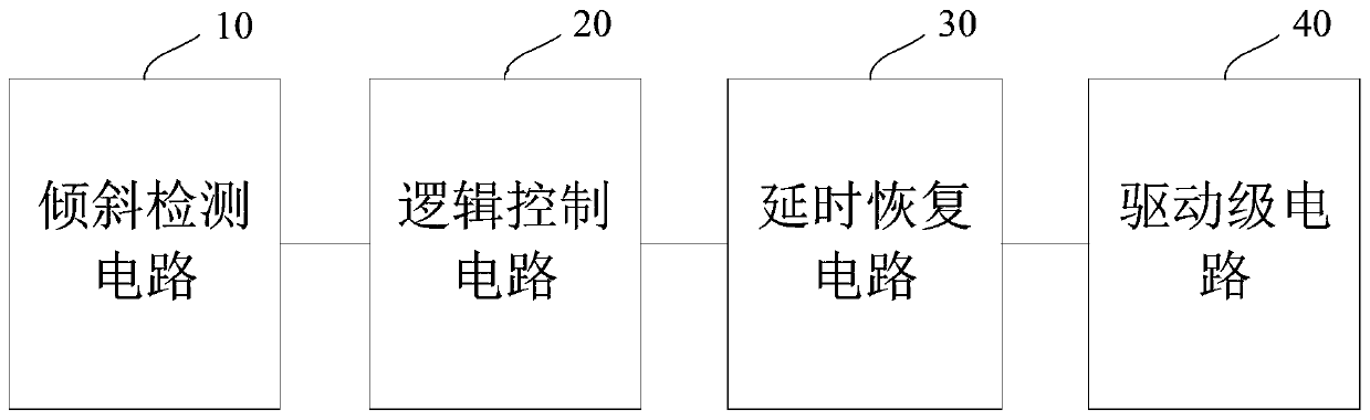
[0047] figure 1 It is a block diagram of a tilt trigger driving circuit shown according to an exemplary embodiment, which is applied to electronic products, and the tilt trigger driving circuit includes a tilt detection circuit 10, a logic control circuit 20, a delay recovery circuit 30 and a driver stage circuit 40 ,in:

[0048] The inclination detection circuit 10 is configured to generate a first detection signal when detecting that the inclination angle of the electronic product is greater than or equal to an angle threshold; the inclination detection circuit 10 is also configured to detect that the inclination angle of the electronic product When it is...


PUM


Abstract

The invention relates to an oblique triggering driving circuit and an electronic product. The oblique triggering driving circuit comprises an oblique detecting circuit, a logic control circuit, a timedelay recovery circuit and a driving stage circuit, wherein the oblique detecting circuit is used for detecting an inclination angle of an electronic product and generating a first detecting signal or a second detecting signal. The logic control circuit is used for generating a charging signal according to the first detecting signal. The logic control circuit is used for generating a dischargingsignal according to the second detecting signal. The driving stage circuit is connected with a time delay recovery circuit and a load power supply loop of the electronic product. The time delay recovery circuit is used for generating a conduction signal according to the charging signal. The time delay recovery circuit is used for generating an off signal according to the discharging signal. The driving stage circuit is used for controlling the load power supply loop to be electrified according to the conduction signal. The driving stage circuit is further used for controlling the load power supply loop to be de-electrified according to the off signal, wherein the time delay recovery circuit generates the conduction signal and/or the off signal in a delayed manner.

Description

technical field [0001] The present disclosure relates to the technical field of circuits, and in particular, relates to a tilt trigger driving circuit and electronic products. Background technique [0002] In related technologies, for some electronic products, such as automatic cleaning equipment, when the inclination angle of the movable part of the cleaning equipment changes to a certain extent due to external force, the automatic cleaning equipment needs to be automatically turned on to enter the working state. When the movable parts return to the self-balancing state, the aforementioned automatic cleaning equipment needs to be turned off. [0003] However, if the tilt angle of the electronic product changes frequently, it may be turned on and off frequently, which will shorten the service life of the electronic product. Contents of the invention [0004] The purpose of the present disclosure is to provide an incline trigger drive circuit and an electronic product, whi...

Claims


Application Information

Patent Timeline
Patent Type & Authority Patents(China)
IPC IPC(8): G05B19/042
CPCG05B19/0423G05B2219/24215
Inventor 王文剑
Owner AEROSPACE INFORMATION
Why Eureka
Try Eureka