Cold ground heat exchange device

A technology of a heat exchange device and a total heat exchanger, applied in the field of heat exchange devices, can solve the problems of damage to the air valve, reduce the accuracy of temperature measurement, and cannot be low in cost, so as to prevent frequent opening and closing, prolong the service life, and improve the Anti-cold wind effect

Active Publication Date: 2017-02-22
PANASONIC ECOLOGY SYSTEMS GUANGDONG CO LTD +1
View PDF7 Cites 0 Cited by
  • Summary
  • Abstract
  • Description
  • Claims
  • Application Information

AI Technical Summary

Problems solved by technology

[0008] 1. When the outdoor temperature is very low, ERV 301 is still running, and the heat exchange device 300 is in the internal circulation state. The hot air in the room will make the temperature at the two-contact temperature control switch 330 rise continuously. When the temperature is higher than the set temperature , the exhaust air valve 316 and the air supply air valve 317 will open, and the cold outdoor air will enter the ERV301 and damage the heat exchanger 305
[0009] 2. When the outdoor cold air enters, the temperature at the two-contact temperature control switch 330 will drop rapidly, and will drop below the set temperature in a short time, so the exhaust air valve 316 and the air supply air The valve 317 will be closed again, which causes the frequent opening and closing of the air valve, thus causing damage to the air valve and reducing the service life
[0010] 3. When the outdoor temperature is very low, ERV 301 still runs, which will cause waste of electric energy
[0011] 4. The cost of the two-contact temperature control switch 330 is relatively high, and the accuracy of temperature measurement is low, with an error of about ±3°C
Moreover, the two-contact temperature control switch 330 cannot be directly replaced by a magnetically sensitive temperature control switch with low cost and high temperature measurement accuracy.
Because the magnetic temperature control switch can withstand a small load, it may be burned
[0012] 5. The size of the temperature control switch bracket 340 is very large, and there is only one opening 343, which affects the flow of air near the temperature control switch bracket 340, thereby reducing the accuracy of temperature measurement by the two-contact temperature control switch 330

Method used


Image

  • Cold ground heat exchange device
  • Cold ground heat exchange device
  • Cold ground heat exchange device

Examples


no. 1 example

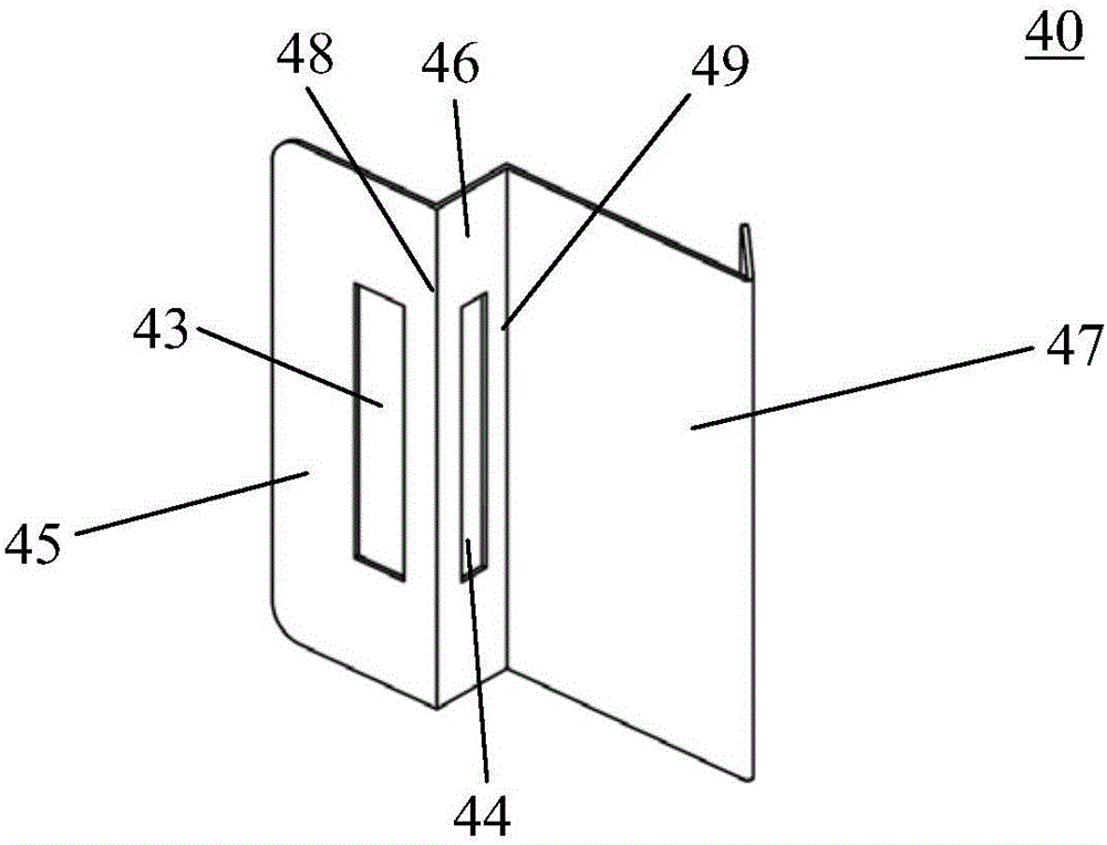
[0036] figure 1 It is a perspective view of the outer case of the cold ground heat exchange device of the first embodiment of the present invention. figure 2 It is a schematic top view of the cold ground heat exchange device in the first embodiment of the present invention when it is in a normal ventilation state. Such as figure 1 and figure 2 As shown, the heat exchange device 100 has an ERV (total heat exchanger) 1 and an outer case 2 mounted on the ERV 1 . An exhaust connection port 24 and an air supply connection port 25 are provided on a side surface of the outer case 2 close to the ERV 1 . An outdoor air outlet 20 and an outdoor air inlet 21 are provided on the side of the outer case 2 away from the ERV 1 .

[0037]A partition plate 11 is arranged in the middle of the outer box 2, and the partition plate 11 divides the outer box 2 into an exhaust channel 3 and an air supply channel 4, and the exhaust channel 3 communicates with the outdoor exhaust port 20 and the...

no. 2 example

[0069] The basic structure of the heat exchange device of this embodiment is the same as that of the first embodiment, and only the differences between this embodiment and the first embodiment will be described below.

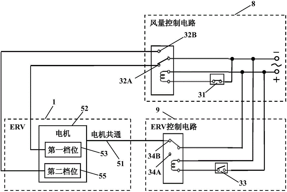
[0070] Figure 6 is a schematic circuit diagram of the heat exchange device of the second embodiment of the present invention. Such as Figure 6 As shown, the ERV 1 includes a motor 52 for driving the ERV 1 to run and a common motor 51 for powering the motor 52 . The motor 52 includes a first gear 53 and a second gear 55 . The first contact 32A of the relay 32 is connected to the first gear 53 of the motor 52 . The second contact 32B is connected to the second gear 55 of the motor 52 . When the temperature T1 is higher than -10°C, the first contact 32A of the relay 32 and the first gear 53 of the motor 52 are connected, and the ERV 1 operates with a large air volume. When the temperature T1 is equal to or lower than -10°C, the second contact 32B of the rel...

no. 3 example

[0077] The basic structure of the heat exchange device of this embodiment is the same as that of the first embodiment, and only the differences between this embodiment and the first embodiment will be described below.

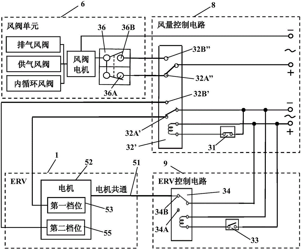
[0078] Figure 7 is a schematic circuit diagram of the heat exchange device of the third embodiment of the present invention. Such as Figure 7 As shown, the ERV 1 includes a motor 52 for driving the ERV 1 to run and a common motor 51 for powering the motor 52 . The motor 52 includes a first gear 53 and a second gear 55 . The double-pole relay 32' of the air volume control circuit 8 includes a first contact 32A', a second contact 32B', a third contact 32A" and a fourth contact 32B". The first contact 32A' is connected to the first gear 53 of the motor 52, the second contact 32B' is connected to the second gear 55 of the motor 52, and the third contact 32A" is connected to the micro switch 36 of the damper unit 6 The first contact 36A of the micro switch is ...


PUM


Abstract

A heat exchange device comprises a total heat exchanger and an outer case. The outer case comprises an exhaust passage for discharging indoor air, an air supply passage for feeding outdoor air into a room, an internal circulation passage for enabling the indoor air to circulate inside the total heat exchanger, an air valve unit, an air volume control circuit and a total heat exchanger control circuit, wherein the air valve unit is used for controlling the open and close of the exhaust passage, the air supply passage and the internal circulation passage; and the air volume control circuit is used for detecting the temperature T1 of one side, close to the total heat exchanger, of the outer case, enables the exhaust passage and the air supply passage to open and the internal circulation passage to close when the temperature T1 is higher than a first set temperature, and enables the internal circulation passage to open and the exhaust passage and the air supply passage to close when the temperature T1 is equal to or lower than the first set temperature; and the total heat exchanger control circuit is used for detecting the temperature T2 of one side, far from the total heat exchanger, of the outer case, enables the total heat exchanger to operate when the temperature T2 is higher than a second set temperature, and enables the total heat exchanger to stop the operation when the temperature T2 is equal to or lower than the second set temperature.

Description

technical field [0001] The invention relates to a heat exchange device, in particular to a cold heat exchange device. Background technique [0002] At present, heat exchanging devices used in cold regions are usually provided with an outer case of the heat exchanging device to prevent the heat exchanging device from freezing. Chinese patent application 200680044567.2 discloses an outer case of a heat exchange device. Such as Figure 8 As shown, the heat exchange device 300 has an ERV (total heat exchanger) 301 and an outer case 302 . On one side of the outer case 302, an outdoor air outlet 320 and an outdoor air inlet 321 are provided. Such as Figure 9 and Figure 10 As shown, the partition plate 311 divides the outer box 302 into an exhaust channel 303 and an air supply channel 304 , and an inner circulation opening 318 is arranged on the partition plate 311 . An exhaust baffle 313 is disposed in the exhaust passage 303 , and an exhaust opening 312 is disposed on the ...

Claims


Application Information

Patent Timeline
Patent Type & Authority Patents(China)
IPC IPC(8): F24F13/20F24F11/00
Inventor 孟东晖赵文雍邱伟周天放高山吉彦
Owner PANASONIC ECOLOGY SYSTEMS GUANGDONG CO LTD
Why Eureka
Try Eureka