Base structure for cleaning equipment and cleaning equipment

A technology for cleaning equipment and surfaces, applied in cleaning equipment, cleaning machinery, cleaning devices, etc., can solve problems such as the inability to effectively prevent UV light leakage from UV lamps, and achieve the effect of avoiding leakage, ensuring normal work, and avoiding frequent opening and closing.

Pending Publication Date: 2021-11-26
KEEWOO ROBOTICS TECH CO LTD
View PDF0 Cites 0 Cited by
  • Summary
  • Abstract
  • Description
  • Claims
  • Application Information

AI Technical Summary

Problems solved by technology

[0004]Based on this, it is necessary to provide a base structure for cleaning equipment and cleaning equipment

Method used


Image

  • Base structure for cleaning equipment and cleaning equipment
  • Base structure for cleaning equipment and cleaning equipment
  • Base structure for cleaning equipment and cleaning equipment

Examples


Embodiment Construction

[0047] In order to make the above objects, features and advantages of the present invention more comprehensible, specific implementations of the present invention will be described in detail below in conjunction with the accompanying drawings. In the following description, numerous specific details are set forth in order to provide a thorough understanding of the present invention. However, the present invention can be implemented in many other ways different from those described here, and those skilled in the art can make similar improvements without departing from the connotation of the present invention, so the present invention is not limited by the specific embodiments disclosed below.

[0048] In describing the present invention, it should be understood that the terms "center", "longitudinal", "transverse", "length", "width", "thickness", "upper", "lower", "front", " Back", "Left", "Right", "Vertical", "Horizontal", "Top", "Bottom", "Inner", "Outer", "Clockwise", "Counte...


PUM


Abstract

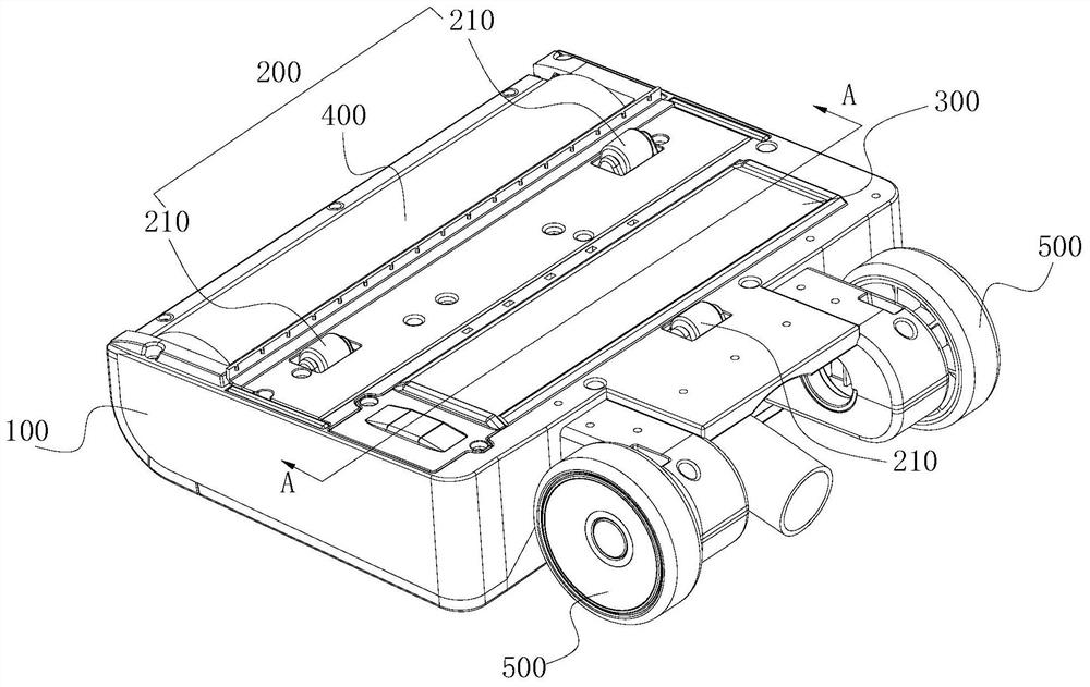
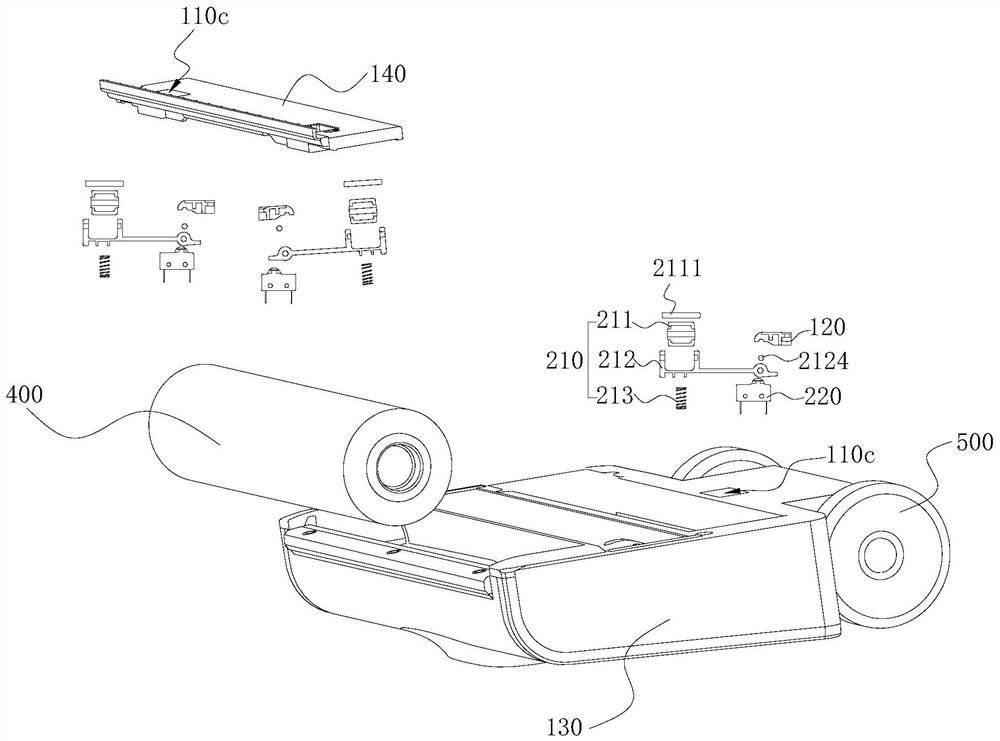
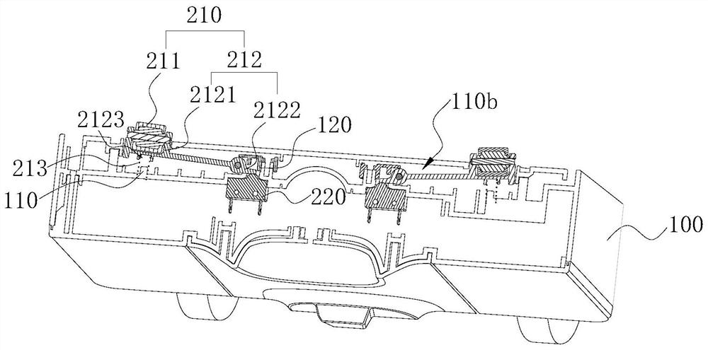
The invention relates to a base structure for cleaning equipment and the cleaning equipment. The base structure comprises a base, a sterilization light leak-proof module and a sterilization module; the sterilization light leak-proof module comprises a control switch and at least three contact pieces, and the contact ends of all the contact pieces are located on different straight lines to form a contact surface; and when the contact ends of all the contact pieces are arranged on a to-be-cleaned face, all the control switches are in an open state to open the sterilization module, and when the contact end of at least one contact piece leaves the to-be-cleaned face and the included angle between the contact face and the to-be-cleaned face is larger than a preset included angle, the control switches are in a closed state to close the sterilization module. The base structure not only can ensure that the base does not leak sterilization light rays generated by the sterilization module in any direction, but also can ensure that the sterilization module works normally when the contact ends of the contact pieces are far away from the to-be-cleaned face.

Description

technical field [0001] The invention relates to the technical field of electrical equipment, in particular to a base structure for cleaning equipment and the cleaning equipment. Background technique [0002] In the existing cleaning equipment, especially household sweepers, in order to avoid harmful microorganisms such as bacteria on the ground after cleaning the ground, an ultraviolet germicidal lamp (UV lamp for short) is usually installed on the bottom of the sweeper base. Specifically, while the roller brush on the base of the sweeper is cleaning the ground, the UV lamp will sterilize the ground within the irradiation range with ultraviolet radiation, so as to remove harmful microorganisms such as bacteria on the current ground, and achieve the purpose of thoroughly cleaning the ground. [0003] Because the UV lamp is sterilized by ultraviolet rays, and the ultraviolet rays will cause great harm to the human body after being irradiated to the human body. Therefore, the t...

Claims


Application Information

Patent Timeline
Patent Type & Authority Applications(China)
IPC IPC(8): A47L11/24A47L11/30A47L11/40A61L2/10
CPCA47L11/24A47L11/302A47L11/40A47L11/405A47L11/4041A47L11/4016A47L11/4083A47L11/4072A61L2/10A47L2201/00A47L2601/10
Inventor 白红太赵登梁
Owner KEEWOO ROBOTICS TECH CO LTD
Why Eureka
Try Eureka