Electrical relay
A relay and electrical technology, applied in the direction of electromagnetic relay, relay, detailed information of electromagnetic relay, etc., can solve problems such as device failure
- Summary
- Abstract
- Description
- Claims
- Application Information
AI Technical Summary
Problems solved by technology
Method used
Image
Examples
no. 1 example
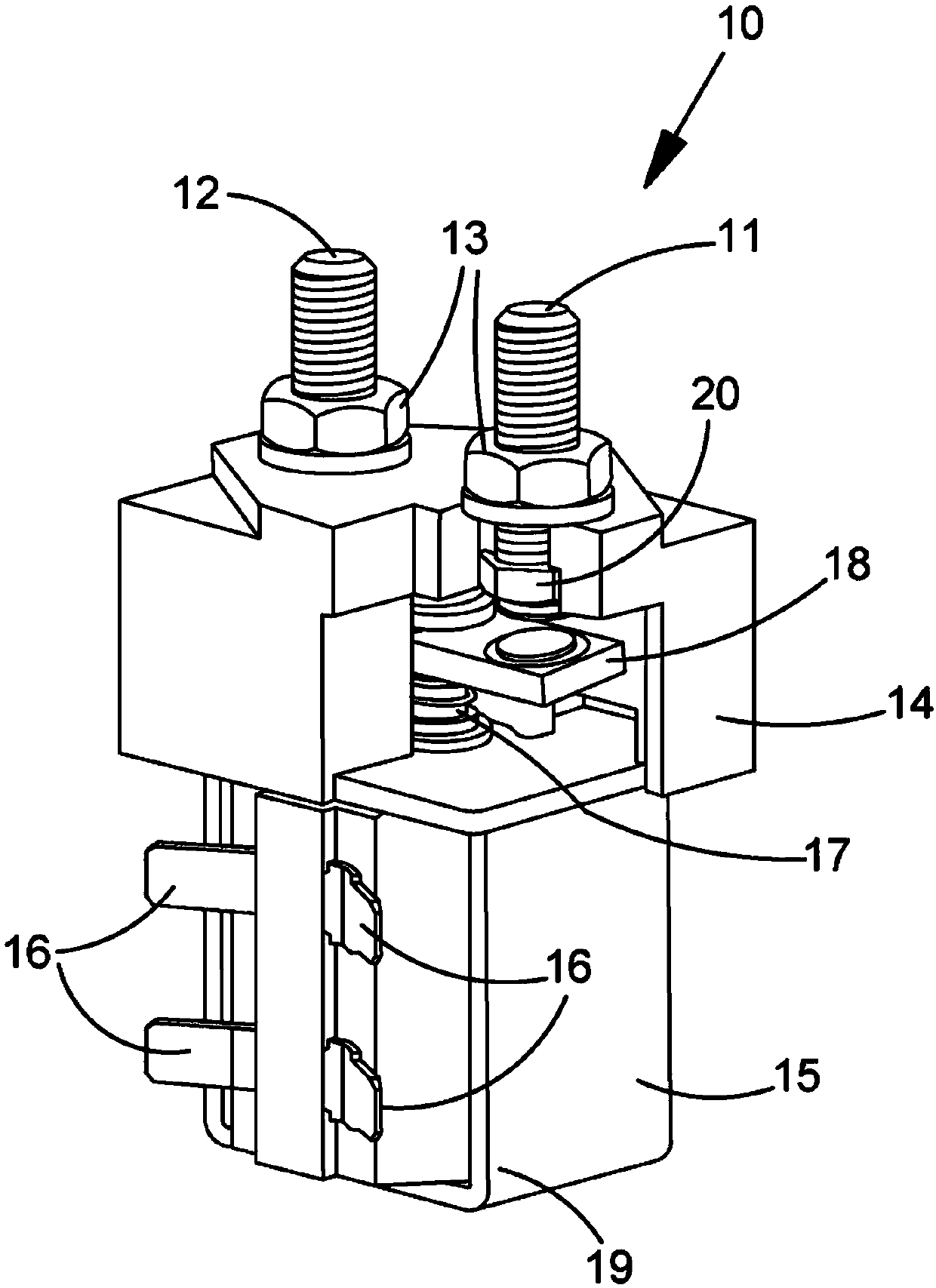
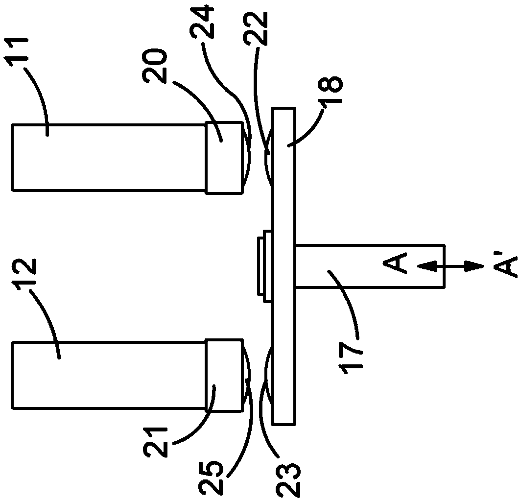
[0047] Figure 5 An assembly of contact bridge member 18 and plunger 17 according to the invention is shown. The touch bridge member has a centrally located vertical hole 27 of a size (diameter) slightly exceeding the outer diameter of the cylindrical body 28 of the plunger. The plunger has a head region 29 which is provided with an annular step 30 . The annular bottom surface 35 of the head region is provided at its outer region with downwardly and radially protruding blocks 31 . The plunger is received in the central bore such that the head region is on the upper side of the bridge and the cylindrical body part protrudes through the bore to below the bridge. Figure 6a and Figure 6b As shown, the plunger is urged against the upper side of the bridge by a helical compression spring 32 and a C-clip spring retainer 33 . An isolating annular spacer 34 isolates the spring from the bridge member.
[0048] Due to the slightly oversized bore, the bridge member can wobble or til...
no. 2 example
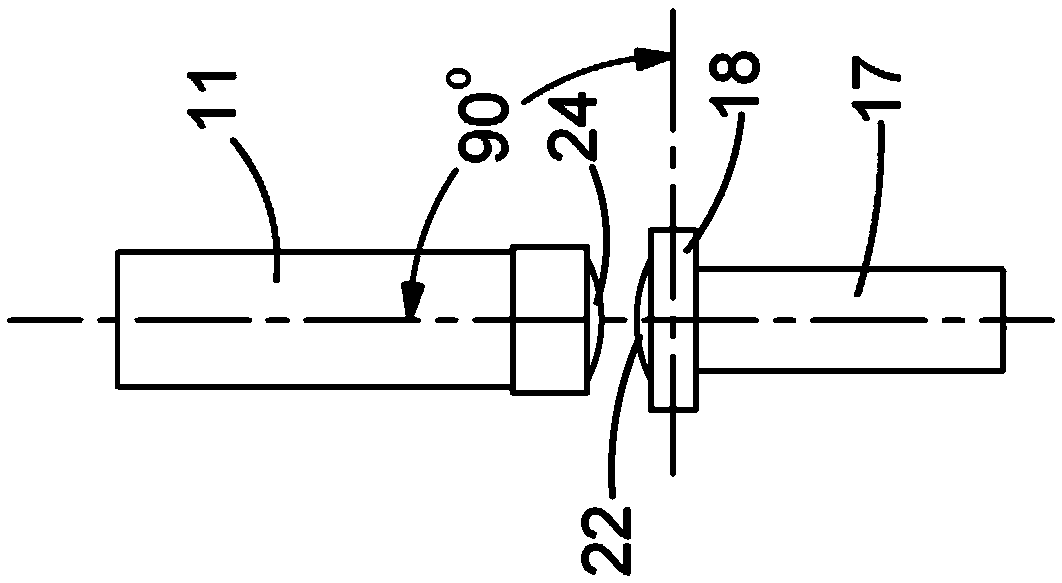
[0055] now refer to Figure 11 to Figure 15 A second embodiment of the invention is described, wherein common parts or features that are also present in the first embodiment are designated with the same reference numerals. In this variant, the bridging member 18 is not provided with a downwardly protruding block 31 for inclining the bridging member 18, but is provided with an upwardly protruding block 40, as in Figure 11 shown. The block is provided at one side of the central hole passing through the bridging member. The head region 29 of the plunger has an annular bottom surface 35 which does not have any downward projection. In this case, the block is pushed against the bottom face 35 of the plunger, which causes the bridge member to tilt about its longitudinal axis (this is allowed due to the tolerance of the larger hole size), which in turn causes the contact pad of the bridge member Tilted relative to fixed contact pads attached to the underside of the pegs 11 , 12 . ...
no. 3 example
[0057] This embodiment has components as previously described for the first and second embodiments, but without the corresponding protruding blocks 31 and 40 . Alternatively, however, a wedge-shaped washer 41 (such as Figure 16 shown). The wedge spacer has a hole for the plunger to pass through with a loose fit. In use, the coil springs 32 push up against the bridge members so that the wedges cause the bridge to assume a tilted orientation. The degree of inclination is determined by the top angle of the wedge. For both the first and second embodiments, the contacts carried by the bridge members 18 will be angled relative to the contacts of the fixed pegs, causing contact to be made at a location away from the center first, and then closed across the center of the pad .
[0058] Given the presence of a wedge-shaped profile, any wedge-shaped planar configuration may be used, for example, such as a generally circular, rectangular, square or irregular shape.
[0059] In othe...
PUM
 Abstract
Description
Claims
Application Information
 - R&D Engineer
- R&D Manager
- IP Professional
- Industry Leading Data Capabilities
- Powerful AI technology
- Patent DNA Extraction
Browse by: Latest US Patents, China's latest patents, Technical Efficacy Thesaurus, Application Domain, Technology Topic.
© 2024 PatSnap. All rights reserved.Legal|Privacy policy|Modern Slavery Act Transparency Statement|Sitemap


