
Bending machine

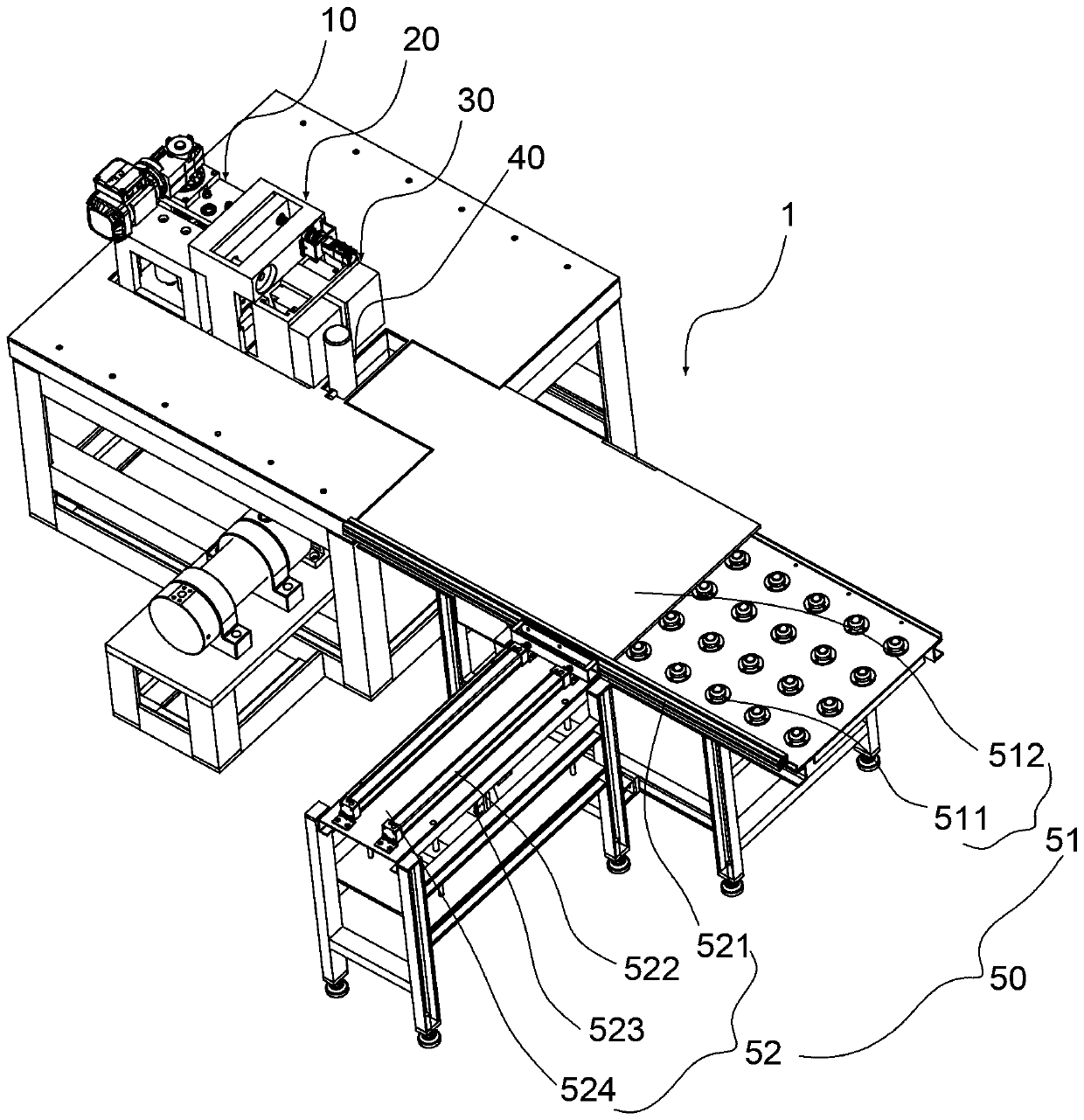
A bending machine and bending die technology, applied in the field of bending machines, can solve the problems of lack of flexibility, and achieve the effects of compact fixture structure, large force ratio and large clamping force.

Pending Publication Date: 2019-05-21
XIAMEN HIPRECISE TECH CO LTD
View PDF0 Cites 1 Cited by
  • Summary
  • Abstract
  • Description
  • Claims
  • Application Information

AI Technical Summary

Problems solved by technology

However, most of the above-mentioned bending machines can only bend long-sized workpieces, and when feeding workpieces, because they do not have the characteristics of flexibility, the workpieces need to be aligned with the feed, so the equipment also needs to have high the accuracy of

Method used


Image

  • Bending machine
  • Bending machine
  • Bending machine

Examples


Embodiment Construction

[0036] Embodiments of the present invention are described in detail below, examples of which are shown in the drawings, wherein the same or similar reference numerals designate the same or similar elements or elements having the same or similar functions throughout. The embodiments described below by referring to the figures are exemplary and are intended to explain the present invention and should not be construed as limiting the present invention.

[0037] In order to better understand the above technical solutions, the following will describe exemplary embodiments of the present invention in more detail with reference to the accompanying drawings. Although exemplary embodiments of the present invention are shown in the drawings, it should be understood that the invention may be embodied in various forms and should not be limited to the embodiments set forth herein. Rather, these embodiments are provided for more thorough understanding of the present invention and to fully c...


PUM


Abstract

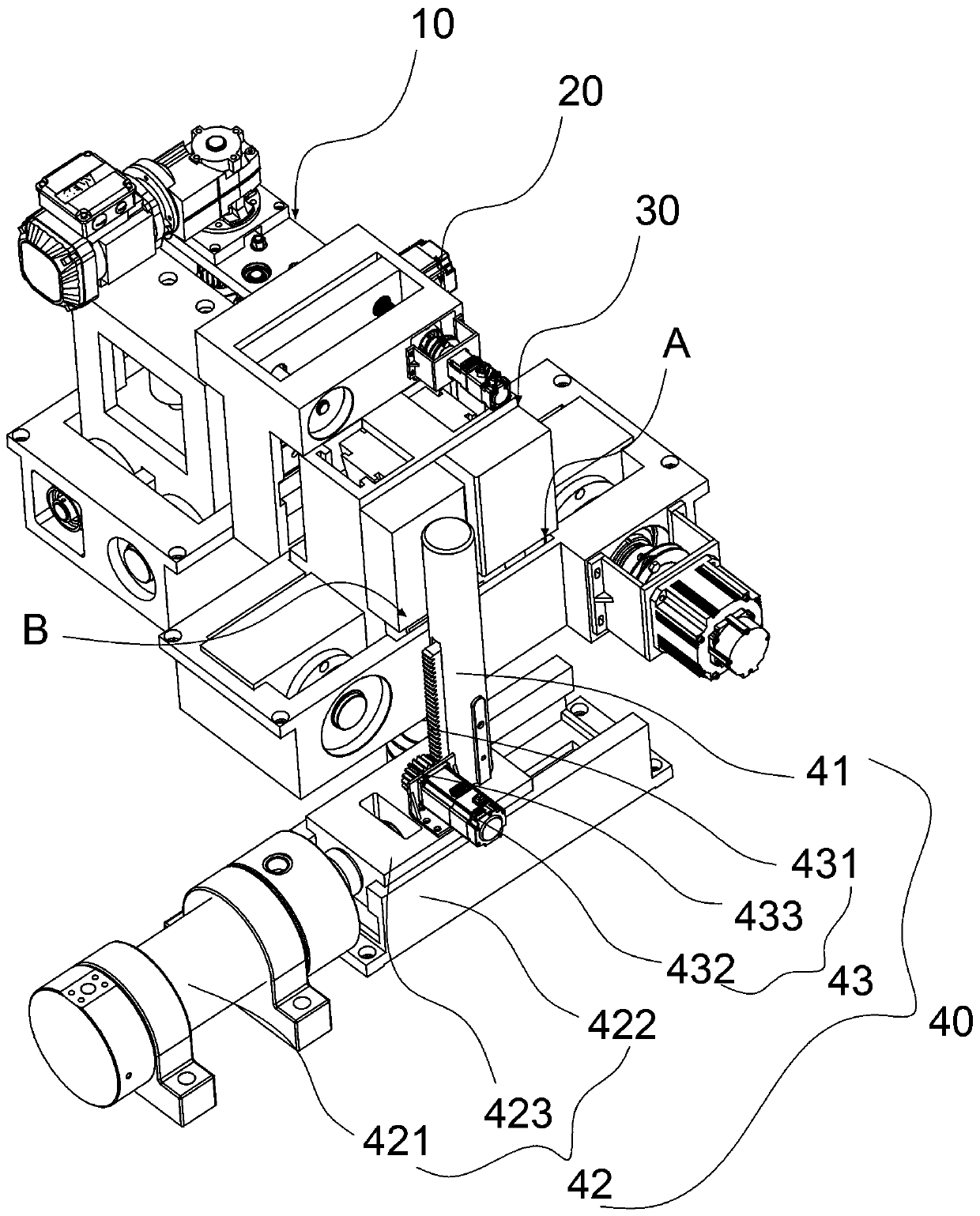
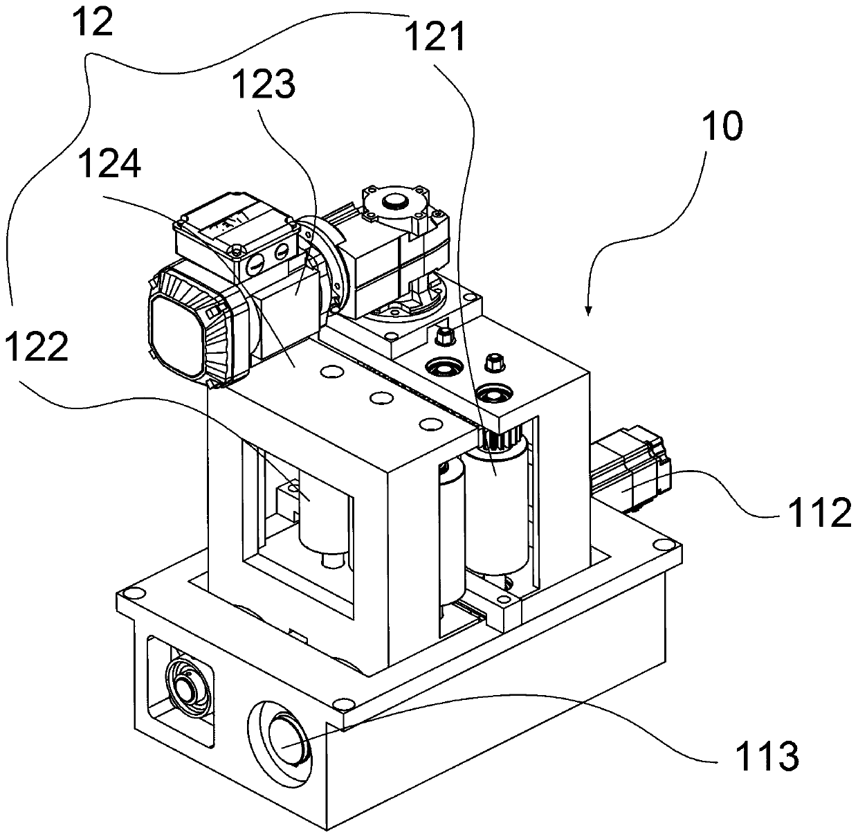
The invention provides a bending machine. The bending machine comprises a feeding device, a transition clamping device, a clamping device and a bending device which are arranged in sequence; the feeding device is provided with a first moving part and two roller shaft sets; the first moving part is connected with the two roller shaft sets for driving the two roller shaft sets to move oppositely; the transition clamping device is provided with a first clamp and a second moving part; the second moving part is connected with the first clamp for driving the first clamp to reciprocate between the feeding device and the clamping device; the clamping device is provided with a second clamp; the second clamp clamps a to-be-bent position of a workpiece, so that the to-be-bent position of the workpiece penetrates out of the second clamp; the bending device comprises a bending die rod and a third moving part for driving the bending die rod to be fed; and the bending die rod is used for being fed tothe workpiece, so that the to-be-bent position of the workpiece is bent by a certain angle relative to the clamped position. Thus, the bending machine is good in flexibility, suitable for bending ofworkpieces of various sizes and capable of achieving automatic bending of workpieces.

Description

technical field [0001] The invention relates to the field of bending processing of metal parts, in particular to a bending machine. Background technique [0002] Traditional metal parts processing, such as the bending of busbars, is a single-machine operation. It is necessary to manually put the busbars into the bending mold and manually adjust the position of the busbars in the bending mold to perform the bending operation, which consumes manpower. The material resources are more, the cost is higher, the processing efficiency of the busbar is lower, and the quality is also uneven. Therefore, the applicant proposes a bending machine capable of automatic feeding, automatic bending, and automatic positioning of busbars, thereby improving the processing efficiency and quality of busbars. However, most of the above-mentioned bending machines can only bend long-sized workpieces, and when feeding workpieces, because they do not have the characteristics of flexibility, the workpie...

Claims


Application Information

Patent Timeline
Patent Type & Authority Applications(China)
IPC IPC(8): B21D7/06B21D43/00B21D43/08
Inventor 曾彬彬陈敏蓝福寿郑榆
Owner XIAMEN HIPRECISE TECH CO LTD
Learn More