
Movable melt container

A container and melt technology, which is applied in the field of smelting melt containers, can solve the problems of laboriousness, easy occurrence of burns, scalds, etc., and achieve the effect of reducing burns

Inactive Publication Date: 2019-05-28
HUNAN JIANXUN ENVIRONMENTAL PROTECTION RESOURCE SCI & TECH DEV
View PDF0 Cites 0 Cited by
  • Summary
  • Abstract
  • Description
  • Claims
  • Application Information

AI Technical Summary

Problems solved by technology

[0003] In order to solve the problem of accidents such as burns and scalds when the smelting melt container is moved manually, and the lack of effort, the present invention provides a movable smelting melt container, which is movable, labor-saving, and can reduce burns, Accidents such as burns

Method used


Image

  • Movable melt container
  • Movable melt container
  • Movable melt container

Examples


Embodiment Construction

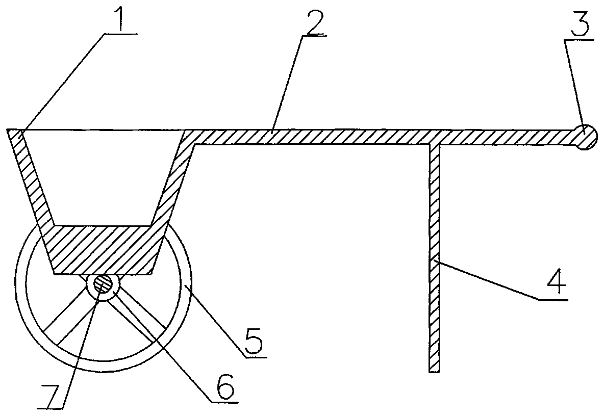
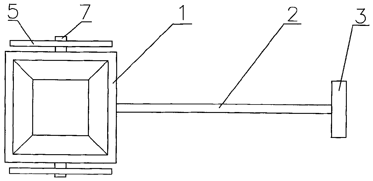
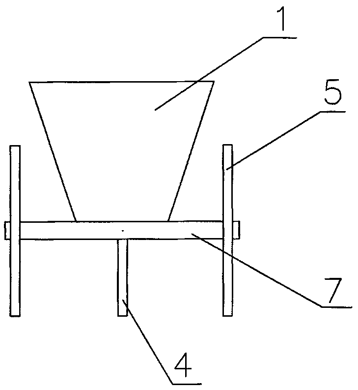
[0015] exist figure 1 , figure 2 , image 3 In the shown embodiment, the upper end of the container 1 is welded with a pull rod 2, the other end of the pull rod 2 is welded with a handle 3, the middle lower part of the pull rod 2 is welded with a leg 4, the bottom of the container 1 is welded with a shaft 7, and the wheel 5 passes through the bearing 6 Connected to both ends of shaft 7.

[0016] When in use, pour the smelting melt into the container 1. After it is full, pick up the handle 3 to lift the feet 4 off the ground, and then drive the container 1, shaft 7, bearing 6, and wheels 5 to move through the pull rod 2. After reaching the destination , the legs 4 touch the ground, and the container 1 is kept stable through the effects of the legs 4, the pull rods 2, the shaft 7, the bearings 6, and the wheels 5.


PUM


Abstract

The invention provides a movable melt container. A pull rod is welded at the upper end of the container, a pull handle is welded at the other end of the pull rod, a support leg is welded at the lowerpart of the middle of the pull rod, a shaft is welded at the bottom of the container, and wheels are connected at two ends of the shaft through bearings.

Description

technical field [0001] The invention relates to a movable smelting melt container. Background technique [0002] At present, the known smelting melt container needs to be manually moved, and there are disadvantages such as burns, scalds and other accidents when manually moving due to the high temperature of the smelting melt, and at the same time, manual moving is laborious, etc. A movable smelting molten container. Contents of the invention [0003] In order to solve the problem of accidents such as burns and scalds when the smelting melt container is moved manually, and the lack of effort, the present invention provides a movable smelting melt container, which is movable, labor-saving, and can reduce burns, Accidents such as burns. [0004] In order to achieve the above object, the technical solution adopted by the present invention to solve the technical problems is designed as follows: [0005] The upper end of the container is welded with a pull rod, the other end ...

Claims


Application Information

Patent Timeline
IPC IPC(8): B62B1/10
Inventor 李建勋
Owner HUNAN JIANXUN ENVIRONMENTAL PROTECTION RESOURCE SCI & TECH DEV
Learn More