A Converter Aging Test System

An aging test and converter technology, applied in the direction of instruments, measuring electricity, measuring devices, etc., can solve the problem of not considering the difference in the demand of the converter, the difference in the requirements of different types and specifications of the converter filter and the voltage level and other problems to achieve the effect of meeting the aging test requirements, enhancing the aging adaptability, and reducing the system cost

Active Publication Date: 2020-12-08
ZHUZHOU CSR TIMES ELECTRIC CO LTD
View PDF8 Cites 0 Cited by
  • Summary
  • Abstract
  • Description
  • Claims
  • Application Information

AI Technical Summary

Problems solved by technology

For example, the common aging test systems on the market can only realize the normal temperature aging of a certain type and specification of converters or inverters, without considering the difference in aging requirements of converters with air-cooled and water-cooled heat dissipation methods, and without considering Different types and specifications of converters have different requirements for filters and voltage levels, etc.

Method used


Image

  • A Converter Aging Test System
  • A Converter Aging Test System
  • A Converter Aging Test System

Examples


Embodiment 1

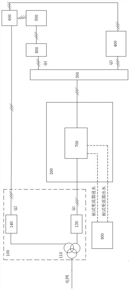
[0033] As mentioned above, aiming at the problem in the prior art that converters of different types and specifications cannot share an aging system according to different aging types, the present invention provides a new converter aging test system. Such as figure 1 As shown, the converter aging test system mainly includes a transformer module 100 , a temperature-controlled aging box 200 , an output selection switch 300 , a motor pairing platform 400 , a filter 500 and a feedback selection switch 600 . in:

[0034] The input terminal of the transformer module 100 is used to connect to the three-phase power grid, and the output terminal of the transformer module 100 includes at least two voltage taps Q1 and Q2, so as to meet the voltage level requirements of different converters. Preferably, the voltage level taps output by the transformer module 100 must at least meet the requirements of three voltage levels.

[0035] For example, the transformer module 100 can be configure...

Embodiment 2

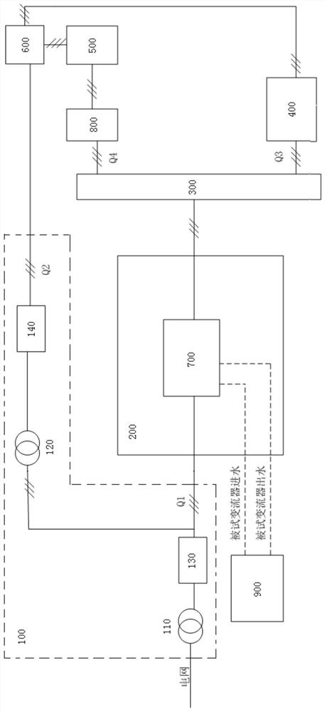
[0045] Such as figure 2 As shown, in Embodiment 2 of the present invention, another form of transformer module 100 is adopted, which can achieve the same technical effect.

[0046] Specifically, the transformer module 110 includes a first transformer 110 and a second transformer 120, wherein:

[0047] The primary side of the first transformer 110 (that is, the input end of the transformer module 100) is connected to the three-phase grid, and the secondary side of the first transformer 110 is connected to the grid-side input end of the tested converter 700 through the first voltage level selection switch 130;

[0048] The primary side of the second transformer 120 is connected to the output terminal of the feedback selection switch 600 through the second voltage level selection switch, and the secondary side of the second transformer 120 is connected to the grid-side input terminal of the tested converter 700 .

[0049] Moreover, the voltage level of the secondary side of the...


PUM


Abstract

The invention discloses a converter aging testing system. The system comprises a transformer module, wherein the input end of the transformer module is connected with a three-phase power grid, a firstvoltage tap at the output end of the transformer module is connected with the network-side input end of a tested converter located in a temperature control aging box, the machine-side output end of the tested converter is connected with the input end of an output selection switch, first-channel output at the output end of the output selection switch is connected with the input end of a motor pairdragging table, second-channel output at the output end of the output selection switch is connected with the input end of a filter, the output end of the filter is connected with the first input endof a feedback selection switch, the second input end of the feedback selection switch is connected with the output end of the motor pair dragging table, and the output end of the feedback selection switch is connected with a second voltage tap at the output end of the transformer module. The system is a general aging system platform used for performing aging testing on converters of different specifications and types.

Description

technical field [0001] The invention relates to an aging test device for converter technology, in particular to a converter aging test system. Background technique [0002] In the existing converter aging test methods, special research and discussions are usually conducted on a certain type of converter or a converter of a certain specification, which fails to fully consider the differentiated needs of different products , failed to make full use of test resources. For example, the common aging test systems on the market can only realize the normal temperature aging of a certain type and specification of converters or inverters, without considering the difference in aging requirements of converters with air-cooled and water-cooled heat dissipation methods, and without considering Different types and specifications of converters have different requirements for filters and differences in voltage levels, etc. Contents of the invention [0003] In view of the above technical...

Claims


Application Information

Patent Timeline
Patent Type & Authority Patents(China)
IPC IPC(8): G01R31/00
Inventor 王新泽唐洲曹洋胡家喜初蕊姚大为邬冬临罗成
Owner ZHUZHOU CSR TIMES ELECTRIC CO LTD
Why Eureka
Try Eureka