New Healthy Air Purifier

An air purifier and healthy technology, applied in air humidification systems, air conditioning systems, air flow control components, etc., can solve problems such as cuts, inaccurate humidity, and difficulty in meeting requirements, and achieve comfortable air outlet, accurate humidity control, and air quality. Accurate wind effect

Active Publication Date: 2021-04-20
宁波德业日用电器科技有限公司
View PDF8 Cites 0 Cited by
  • Summary
  • Abstract
  • Description
  • Claims
  • Application Information

AI Technical Summary

Problems solved by technology

[0003] 1. The angle of the air outlet louvers on the air outlet of the electric fan is pre-set. Once set, it cannot be changed, resulting in the inability to adjust the size of the air outlet. Moreover, there is a gap between two adjacent louvers in the current air outlet. At the same time, because the air outlet louvers are aligned with the internal fan blades, it is easy for children to insert their fingers into the fan and be cut;
[0004] 2. The air outlet of the electric fan can only be opened but not closed. At the same time, the size of the air outlet cannot be adjusted. In addition, because the air outlet cannot be closed, there is a safety hazard. For fans with side air outlet, since the air outlet is on the side, if the fan is close to the human body, it is easy to cause the air outlet to blow directly on the person. If the wind speed is fast, it is easy to catch a cold, and the wind direction is always towards the people, making it very uncomfortable and not gentle;
[0005] 3. The electric fan cannot realize automatic temperature control operation, resulting in only receiving control, resulting in poor intelligent effect;
[0006] 4. The existing humidifier installed in the electric fan generally adopts the method of waterwheel to enter the water, and the water inflow and outflow can not be controlled, resulting in the indoor humidity is not accurate enough to meet the requirements

Method used


Image

  • New Healthy Air Purifier
  • New Healthy Air Purifier
  • New Healthy Air Purifier

Examples


Embodiment 1

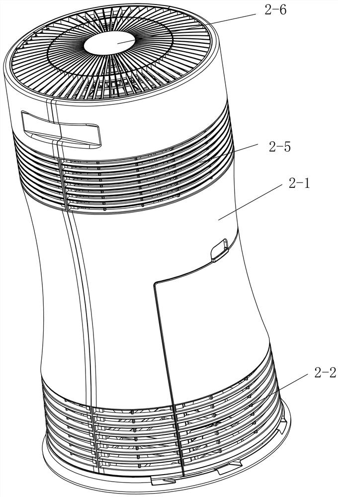
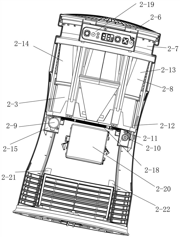
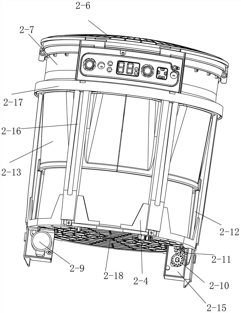
[0039] Such as figure 1 , figure 2 , Figure 12 , Figure 13 , Figure 14 , Figure 15 , Figure 16 , Figure 17 As shown, a new healthy air purifier provided by this embodiment includes an annular housing 2-1, an air inlet 2-2 is provided on the lower side wall of the annular housing 2-1, and an air inlet 2-2 is provided on the lower side wall of the annular housing 2-1. A vortex fan assembly is provided inside, and the vortex fan assembly includes a vortex fan 2-3 and a vortex fan bracket 2-4. The upper side wall of the upper side wall is provided with the first air outlet 2-5 of 360° circular omnidirectional distribution, and the said vortex fan 2-3 is horizontally aligned with the first air outlet 2-5, and the upper side of the annular shell 2-1 is set There is a second air outlet 2-6, the second air outlet 2-6 is provided with a crankshaft adjustment mechanism 2-7 that can change the size of the second air outlet 2-6 or completely close, and the first air outlet 2...


PUM


Abstract

The invention discloses a new healthy air purifier, which comprises an annular shell, an air inlet is arranged on the lower side wall of the annular shell, a vortex fan assembly is arranged in the annular shell, and a The first air outlet is distributed in a 360° ring in all directions, the second air outlet is provided above the annular shell, and the crankshaft adjustment mechanism that can change the size of the second air outlet or close it all is provided below the second air outlet. The first air outlet is equipped with an air outlet adjustment mechanism that can completely close the first air outlet and let the air flow out from the second air outlet. A temperature display screen is installed above the annular housing, and a humidifier is also installed in the annular housing. As well as a controller electrically connected to the temperature display screen, a temperature sensor and a humidity sensor are arranged at the air inlet, and the controller is electrically connected to the air outlet regulating mechanism and the crankshaft regulating mechanism. This structure realizes comfortable air outlet, automatic temperature control, changing air outlet mode according to needs, and more precise humidity control.

Description

technical field [0001] The invention relates to the technical field of a fan, in particular to a new healthy air purifier. Background technique [0002] With the development of society, people's requirements for quality of life are constantly improving, and smart home has become a future development trend. Smart electric fans are devices that use electricity to generate airflow and realize intelligent control. The wind is used to achieve the effect of enjoying the cool, but the current electric fan has the following problems: [0003] 1. The angle of the air outlet louvers on the air outlet of the electric fan is pre-set. Once set, it cannot be changed, resulting in the inability to adjust the size of the air outlet. Moreover, there is a gap between two adjacent louvers in the current air outlet. At the same time, because the air outlet louvers are aligned with the internal fan blades, it is easy for children to insert their fingers into the fan and be cut; [0004] 2. The...

Claims


Application Information

Patent Timeline
Patent Type & Authority Patents(China)
IPC IPC(8): F24F8/80F24F8/125F24F6/04F24F13/28F24F11/89F24F11/52F24F13/10
Inventor 喜内一彰村田浩贵水谷一弘
Owner 宁波德业日用电器科技有限公司
Why Eureka
Try Eureka