
Projection device for automatic office

A technology for automated office and projection devices, applied in projection devices, optics, instruments, etc., can solve the problems of weak resistance to bending, loss of rods, affecting the projection effect of projectors, etc.

Inactive Publication Date: 2019-06-25
XIAN LIYUAN INTELLIGENT TECH
View PDF0 Cites 1 Cited by
  • Summary
  • Abstract
  • Description
  • Claims
  • Application Information

AI Technical Summary

Problems solved by technology

[0003] Since the projector and the roof in the office are only connected by a rod, and the rod's ability to resist bending is not strong, this leads to even a small external interference, such as wind, vibration, etc., will make the projection There is a relative deviation between the projector and the initial installation position. In addition, in addition to the telescopic rod, the projector hanger has other connecting mechanisms. Due to the relative sliding between the screws and the connecting parts, the relative initial position of the projector will also be caused. Deviation of installation position
The direct result of the deviation is that the image projected by the projector deviates from the projection screen, causing part of the image to be deformed or lost, which affects the projection effect of the projector, and at the same time brings visual discomfort to the user. It can only be found and adjusted when the projector is turned on. At the same time, the adjustment process is time-consuming and dangerous. Therefore, we urgently need to design an automated office projection device to solve the above problems.

Method used


Image

  • Projection device for automatic office
  • Projection device for automatic office
  • Projection device for automatic office

Examples


Embodiment Construction

[0017] The following will clearly and completely describe the technical solutions in the embodiments of the present invention with reference to the accompanying drawings in the embodiments of the present invention. Obviously, the described embodiments are only some, not all, embodiments of the present invention.

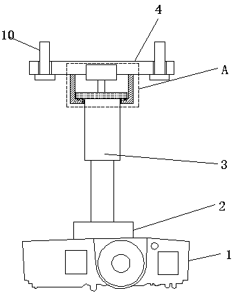
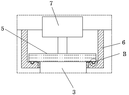
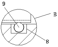
[0018] refer to Figure 1-3 , a projection device for automated office use, including a mounting base 4, a fixing frame 6 is fixedly welded on one side of the mounting base 4, and an opening is opened on the side of the fixing frame 6 away from the mounting base 4, and the two sides of the mounting base 4 A screw positioning buckle 10 is provided, and the opening of the fixed frame 6 is fixedly equipped with a bearing, and the opening of the fixed frame 6 is movably provided with a telescopic support rod 3, and the telescopic support rod 3 is provided with an extension rod, and the extension rod is fixedly welded on the connection On the seat 2, a projector 1 is fixe...


PUM


Abstract

The invention discloses a projection device for automatic office. The projection device for automatic office comprises a mounting base, wherein a fixing frame is fixedly welded on one side surface ofthe mounting base, an opening is formed in the side, away from the mounting base, of the fixing frame, a bearing is fixedly arranged at the opening of the fixing frame, a telescopic supporting rod ismovably arranged at the opening of the fixing frame, one end of the telescopic supporting rod extends into the fixing frame movably through the bearing opening in the fixing frame, the inner wall of the bearing is connected to the outer side of the telescopic supporting rod, the other end of the telescopic supporting rod is vertically arranged right below the fixing frame, and a connecting seat isfixedly welded to the end, away from the fixing frame, of the telescopic supporting rod. In the projection device for automatic office, a rotating motor which can rotate is arranged in the mounting base, so that the rotating motor drives a projector to rotate, and when the projector deviates, adjustment can be carried out without manual adjustment at a high place, and the deviation of the projector can be adjusted by directly controlling the rotation of the rotating motor.

Description

technical field [0001] The invention relates to the technical field of office supplies, in particular to a projection device for automatic office use. Background technique [0002] A projector, also known as a projector, is a device that can project images or videos onto a screen. It can be connected to a computer, VCD, DVD, BD, game console, DV, etc. through different interfaces to play the corresponding video signal. With the continuous advancement of technology, projectors have been put into various aspects, and some companies will also install projectors in their offices for multimedia meetings. [0003] Since the projector and the roof in the office are only connected by a rod, and the rod's ability to resist bending is not strong, this leads to even a small external interference, such as wind, vibration, etc., will make the projection There is a relative deviation between the projector and the initial installation position. In addition, in addition to the telescopic r...

Claims


Application Information

Patent Timeline
Patent Type & Authority Applications(China)
IPC IPC(8): F16M13/02F16M11/18F16M11/06G03B21/54
Inventor 王翊婷
Owner XIAN LIYUAN INTELLIGENT TECH
Learn More