Resistance test fixture

A resistance testing and jig technology, which is used in the testing of single semiconductor devices, measuring resistance/reactance/impedance, components of electrical measuring instruments, etc., which can solve the problem that the probe cannot contact the port of the resistor and cannot accurately realize the resistance value of the resistor. Problems such as low accuracy of measurement and manual adjustment of probes

Pending Publication Date: 2019-06-28
SHENZHEN JPT OPTO ELECTRONICS CO LTD
View PDF6 Cites 5 Cited by
  • Summary
  • Abstract
  • Description
  • Claims
  • Application Information

AI Technical Summary

Problems solved by technology

[0002] In the process of mass production of chip resistors, sampling inspection is required, and multiple pieces are selected from the same batch of resistors for resistance measurement; when performing resistance measurement, it is necessary to use two sets of probes to be close to the ports at both ends of the resistor; The specifications of different batches of resistors are different, and the spacing between the ports on both sides of resistors with different specifications is different. The existing solutions generally adjust the probes manually so that the spacing between the two sets of probes corresponds to the spacing between the terminals on both sides of the resistor. However, manual adjustment The precision of the probe is low, so that the probe cannot be in contact with the port of the resistor, and the resistance value measurement of the resistor cannot be accurately realized

Method used


Image

  • Resistance test fixture
  • Resistance test fixture
  • Resistance test fixture

Examples


Embodiment Construction

[0022] In order to facilitate the understanding of the present invention, the following will describe the present invention more fully. However, the present invention can be embodied in many different forms and is not limited to the embodiments described herein. On the contrary, these embodiments are provided to make the understanding of the disclosure of the present invention more thorough and comprehensive.

[0023] Unless otherwise defined, all technical and scientific terms used herein have the same meaning as commonly understood by one of ordinary skill in the technical field of the invention. The terms used herein in the description of the present invention are for the purpose of describing specific embodiments only, and are not intended to limit the present invention.

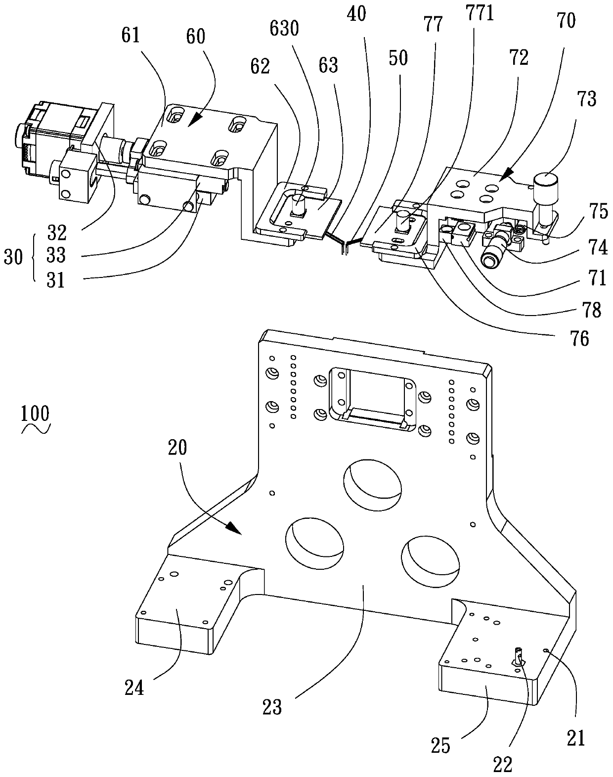
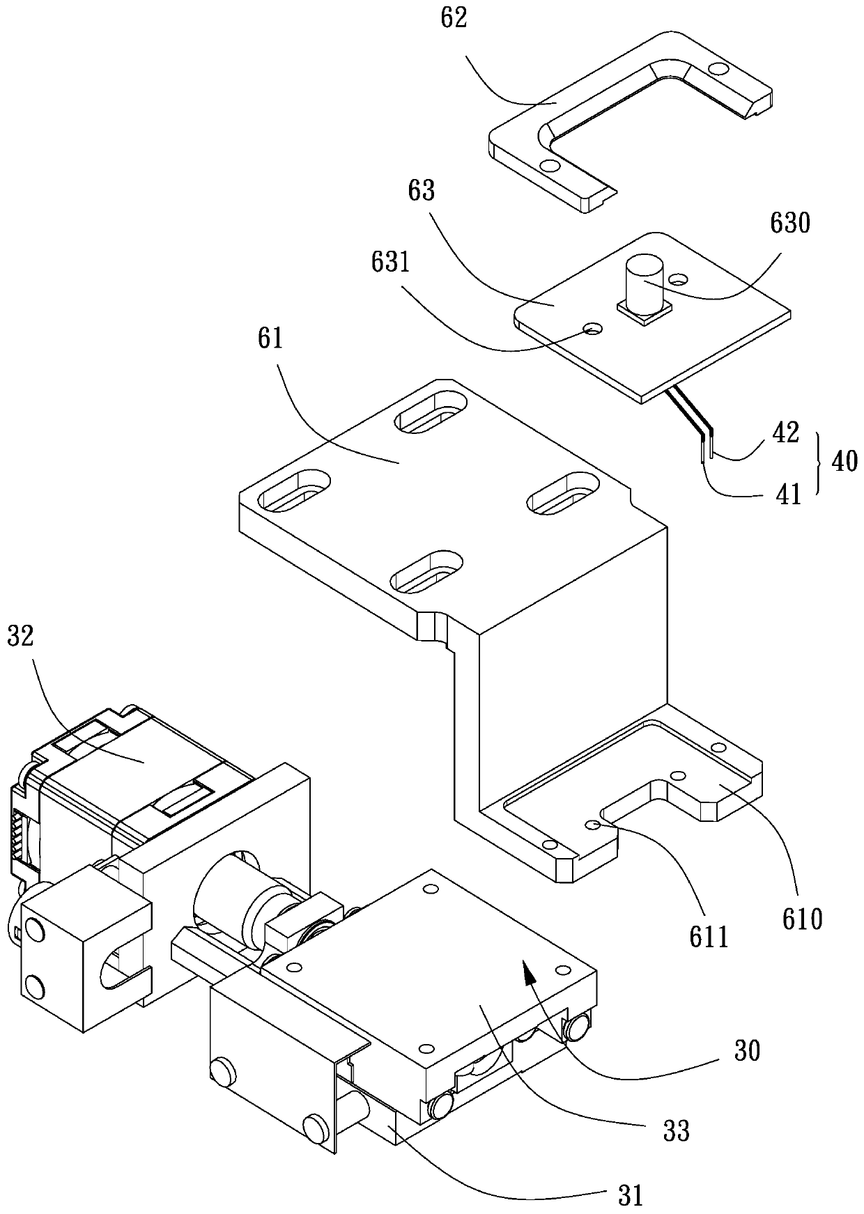
[0024] see Figure 1 to Figure 7 , is a resistance test fixture 100 according to a preferred embodiment of the present invention, and is used for connecting the probe to the resistance port. The resis...


PUM


Abstract

Provided in the invention is a resistance test fixture comprising a substrate, an electric linear module mounted on the substrate, a movable probe assembly connected to the electric linear module, anda fixed probe assembly connecting the substrate. The electric linear module includes a base connected to the substrate, a driving motor connected to the base, and a sliding table disposed on the basein a sliding manner. The movable probe assembly is connected to the sliding table; and driving motor drives the sliding table to drive the movable probe assembly to move relative to the fixed probe assembly. The fixed probe assembly and the movable probe assembly correspond to each other. In addition, the invention also includes a first carrier assembly connecting the sliding table; the first carrier assembly includes a first adapter plate connected to the sliding table, a first clamp plate connected to the first adapter plate, and the first carrier plate. The driving motor drives the slidingtable to move relative to the base. Since the movable probe assembly is connected to the sliding table and the fixed probe assembly is connected to the substrate, the distance between the movable probe assembly and the fixed probe assembly can be precisely adjusted, so that the distance corresponds to the distance between the two ports of the resistor accurately.

Description

technical field [0001] The invention relates to a test auxiliary device, in particular to a resistance test jig. Background technique [0002] In the process of mass production of chip resistors, sampling inspection is required, and multiple pieces are selected from the same batch of resistors for resistance measurement; when performing resistance measurement, it is necessary to use two sets of probes to be close to the ports at both ends of the resistor; The specifications of different batches of resistors are different, and the spacing between the ports on both sides of resistors with different specifications is different. The existing solutions generally adjust the probes manually so that the spacing between the two sets of probes corresponds to the spacing between the terminals on both sides of the resistor. However, manual adjustment The precision of the probe is low, so that the probe cannot be in contact with the port of the resistor, and the resistance value measurem...

Claims


Application Information

Patent Timeline
Patent Type & Authority Applications(China)
IPC IPC(8): G01R27/02G01R1/067
CPCG01R27/02G01R1/067G01R31/26
Inventor 许根夫陆志华
Owner SHENZHEN JPT OPTO ELECTRONICS CO LTD
Why Eureka
Try Eureka