Special fixture for batch numerical control machining of centrifugal impeller with non-through-hole center and mounting method

A centrifugal impeller and special fixture technology, applied in clamping devices, manufacturing tools, metal processing equipment, etc., can solve the problems of reducing processing accuracy and processing efficiency, achieve consistent benchmarks, avoid low processing efficiency, and large parts support area. Effect

Active Publication Date: 2019-07-12
NORTHWESTERN POLYTECHNICAL UNIV
View PDF5 Cites 1 Cited by
  • Summary
  • Abstract
  • Description
  • Claims
  • Application Information

AI Technical Summary

Problems solved by technology

[0006] Aiming at the problems that the centrifugal impeller with a non-through hole in the center cannot be clamped by the tensioning method of the tie rod, and the secondary clamping method is required by the pressure plate pressing method, thereby reducing the processing accuracy and processing efficiency, the present invention provides a stable clamping and precise positioning The special fixture for batch processing of centrifugal impellers with non-through holes in the center can quickly clamp and position centrifugal impellers in batch processing by performing one-time clamping and alignment on the fixture, which avoids low processing efficiency and positioning benchmarks caused by multiple alignments of parts Inconsistency and other issues

Method used


Image

  • Special fixture for batch numerical control machining of centrifugal impeller with non-through-hole center and mounting method
  • Special fixture for batch numerical control machining of centrifugal impeller with non-through-hole center and mounting method
  • Special fixture for batch numerical control machining of centrifugal impeller with non-through-hole center and mounting method

Examples


Embodiment Construction

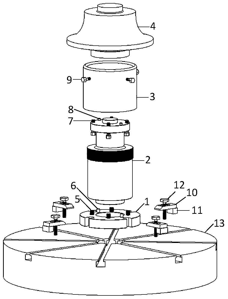
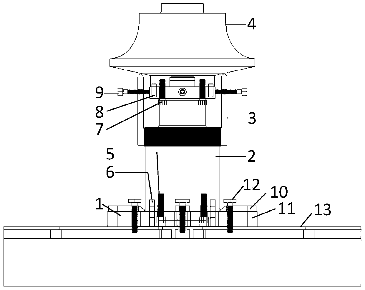
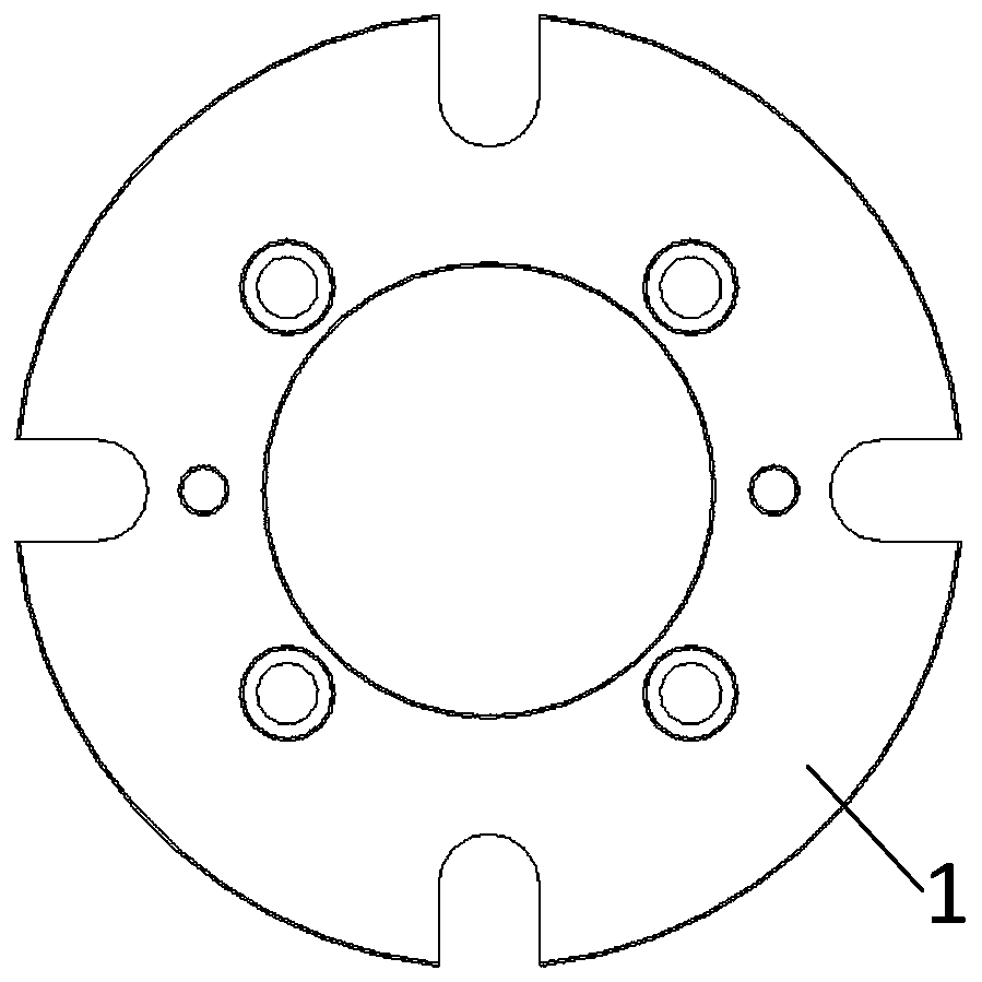
[0041] Embodiments of the present invention are described in detail below, examples of which are shown in the drawings, wherein the same or similar reference numerals designate the same or similar elements or elements having the same or similar functions throughout. The embodiments described below by referring to the figures are exemplary and are intended to explain the present invention and should not be construed as limiting the present invention.

[0042] In describing the present invention, it should be understood that the terms "center", "longitudinal", "transverse", "length", "width", "thickness", "upper", "lower", "front", " Orientation indicated by rear, left, right, vertical, horizontal, top, bottom, inside, outside, clockwise, counterclockwise, etc. The positional relationship is based on the orientation or positional relationship shown in the drawings, which is only for the convenience of describing the present invention and simplifying the description, rather than ...


PUM


Abstract

The invention discloses a special fixture for batch numerical control machining of a centrifugal impeller with a non-through-hole center and a mounting method of the special fixture. The mounting method comprises the following steps that a fixture shaft sleeve sleeves a fixture connecting shaft from the bottom of the fixture connecting shaft, the fixture connecting shaft is connected with a fixture base through base bolts, and the fixture connecting shaft is positioned through base pins; the fixedly-connected fixture base is fixed on a machine tool workbench, and a fixture connecting shaft outer circle is aligned on a machine tool; when each centrifugal impeller is machined, a centrifugal impeller blank is placed on the fixture connecting shaft, connecting shaft bolts are used for connecting the centrifugal impeller blank with the fixture connecting shaft, and meanwhile, connecting shaft pins are used for positioning the centrifugal impeller blank; and the fixture shaft sleeve is screwed from bottom to top until the upper end face of the fixture shaft sleeve abuts against the bottom of the centrifugal impeller blank, and shaft sleeve bolts are tightened to prevent the fixture shaftsleeve from loosening. According to the special fixture for batch numerical control machining of the centrifugal impeller with the non-through-hole center and the mounting method of the special fixture, numerical control machining clamping positioning of the centrifugal impeller can be realized, repeated alignment of a part is avoided, and then the machining precision and the machining consistency of the centrifugal impeller are ensured.

Description

technical field [0001] The invention relates to the field of centrifugal impeller processing, in particular to a special fixture and installation method for numerically controlled machining of a centrifugal impeller with a non-through hole in the center. Background technique [0002] Centrifugal impellers are the core components of compressors, expanders, propellers and other mechanisms, and are widely used in aviation, aerospace, shipping, petrochemical, metallurgy, weapon manufacturing and other fields. In recent years, with the continuous improvement of design requirements and the continuous shortening of the research and development cycle, the design structure of the centrifugal impeller has changed, and the precision and efficiency requirements of its CNC machining have also been continuously improved. Therefore, it is necessary to develop a special CNC machining fixture suitable for the new structure of the centrifugal impeller, and quickly clamp and position the centr...

Claims


Application Information

Patent Timeline
Patent Type & Authority Applications(China)
IPC IPC(8): B23Q3/00
CPCB23Q3/00B23Q2703/10
Inventor 梁永收许迎颖任军学温长喜
Owner NORTHWESTERN POLYTECHNICAL UNIV
Why Eureka
Try Eureka