A metal workpiece edge folding machine with three degrees of freedom

A technology of metal workpieces and degrees of freedom, applied in metal processing equipment, forming tools, manufacturing tools, etc., can solve the problems of affecting the rigidity and strength of the mold, poor flexibility, and easy interference with the workpiece, so as to avoid interference collision and edge folding The effect of high precision and large bending angle

Active Publication Date: 2022-01-04
南京云上自动化科技有限公司
View PDF11 Cites 0 Cited by
  • Summary
  • Abstract
  • Description
  • Claims
  • Application Information

AI Technical Summary

Problems solved by technology

[0005] 1. The above-mentioned horizontal driving mechanism has additional swing while moving in the horizontal direction; the vertical driving mechanism also has additional swing while driving the vertical direction movement, so it cannot realize the two freedoms in the X and Y directions in the absolute sense. single degree of motion translation, not to mention the degree of freedom of rotation, so it cannot adapt to the bending of many complex workpieces
[0006] 2. When the bending angle is large, the hemming mold of the mold is easy to interfere with the blanking mold. Therefore, in order to achieve a large angle of bending, it is usually necessary to remove the material at the mold interference position, which will seriously affect the rigidity of the mold and intensity
[0007] 3. There are only 2 degrees of freedom mechanisms in the above comparison documents. During the bending process, sliding between the plate and the tip of the folding die is inevitable, so the indentation on the surface of the bending workpiece is inevitable.
[0008] 4. The two degrees of freedom in the above comparison documents have poor flexibility and are likely to interfere with the workpiece during the bending process

Method used


Image

  • A metal workpiece edge folding machine with three degrees of freedom
  • A metal workpiece edge folding machine with three degrees of freedom
  • A metal workpiece edge folding machine with three degrees of freedom

Examples


Embodiment approach 1

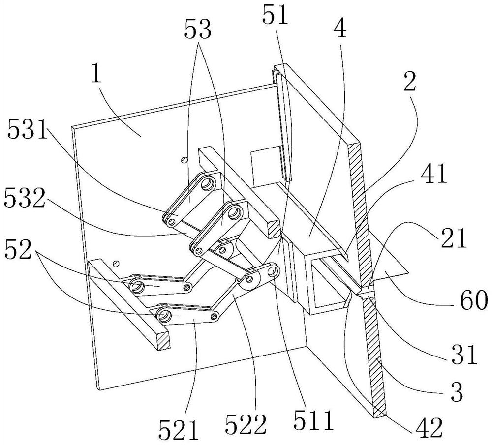
[0047] Such as figure 1 As shown, the slider is vertically slidably installed on the frame directly above the fixed block, and the upper die slides vertically up and down with the slider to achieve height adjustment.

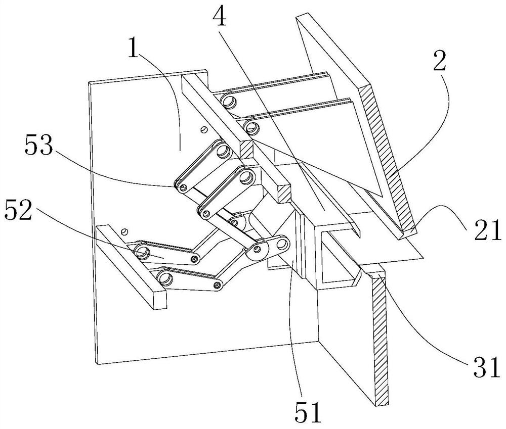
[0048] Second embodiment

[0049] Such as figure 2 As shown, the slider is flipped and installed on the frame directly above the fixed block, and the upper die is flipped with the slider to achieve height adjustment.

[0050] A hemming die is installed on the hemming beam, and the hemming die is used for hemming the metal workpiece, including a hemming upper die 41 and a hemming lower die 42 . In this embodiment, the hemming beam is preferably C-shaped, and the hemming upper die 41 and the hemming lower die 42 are respectively arranged at the C-shaped opening of the hemming beam.

[0051] Under the action of the hemming transmission mechanism, the hemming beam can move in three degrees of freedom, horizontally, vertically and rotationally.

[0052] The hemm...


PUM


Abstract

The invention discloses a metal workpiece hemming machine with three degrees of freedom, which comprises a machine frame, a hemming die, a hemming beam and a hemming transmission mechanism; Three degrees of freedom, vertical and rotational; the hemming transmission mechanism includes the hemming beam driving shaft, the first crank linkage mechanism and the second crank linkage mechanism; the hemming beam driving shaft is used to drive the hemming beam Rotation; the other end of the first crank is hinged on the frame and rotates synchronously; the other end of the first connecting rod is hinged on the flange beam drive shaft; the other end of the second crank is hinged on the frame and rotates synchronously; The other ends of the second connecting rods are respectively hinged on the corresponding first connecting rods. The present invention cooperates with each other through the three drive components of the first and second crank-link mechanisms and the flanged beam drive shaft, so as to realize the movement of three degrees of freedom in the horizontal direction, vertical direction and rotation, and during the movement process, There is no swinging attachment, and the folding precision is high.

Description

technical field [0001] The invention relates to an edge folding device, in particular to a metal workpiece edge folding machine with three degrees of freedom. Background technique [0002] The edge folding machine is a simple bending machine, which can be operated manually or motorized. The edge folding machine is a mechanical device for processing the edge of the product. The existing traditional edge folding machine can only realize a single up and down folding action, and cannot Realize complex hemming trajectories. With the development of social economy, people's needs for workpieces are becoming wider and wider, and traditional folding machines cannot meet customer needs. In addition, the structure of the traditional folding machine is too simple, the transmission precision is low, and the product quality is poor. [0003] The Chinese invention patent application with the application number CN201610497320.1, the name of its invention is "a metal sheet material folding...

Claims


Application Information

Patent Timeline
Patent Type & Authority Patents(China)
IPC IPC(8): B21D19/08B21D37/12B21D37/00
CPCB21D19/08B21D37/12B21D37/00
Inventor 徐丰羽李剑陈自新
Owner 南京云上自动化科技有限公司
Why Eureka
Try Eureka