Supercharge Your Innovation With Domain-Expert AI Agents!

Door lock device for vehicle and installation method thereof

A technology for car doors and door locks, which is applied in the field of vehicle door lock devices, and can solve problems such as difficulty in the movement and connection of door lock rotors

Active Publication Date: 2022-01-07
MAZDA MOTOR CORP +1
View PDF9 Cites 0 Cited by
  • Summary
  • Abstract
  • Description
  • Claims
  • Application Information

AI Technical Summary

Problems solved by technology

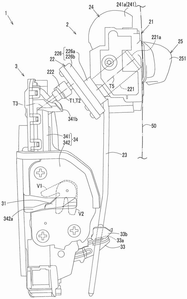
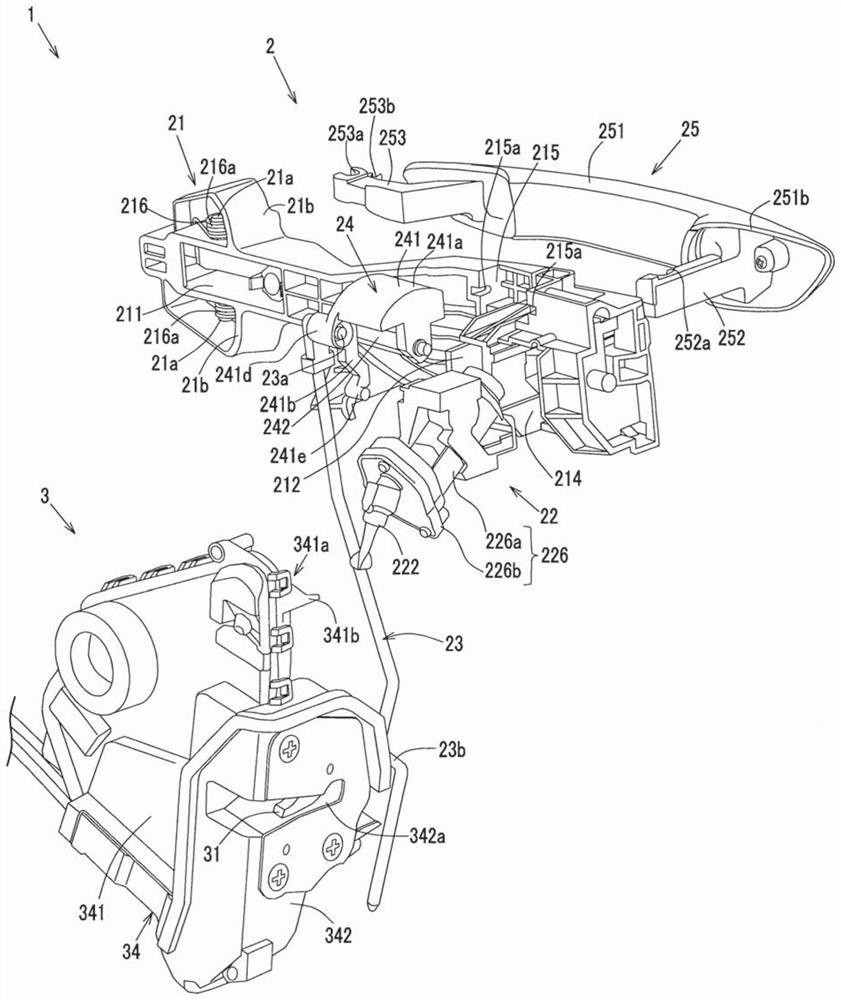
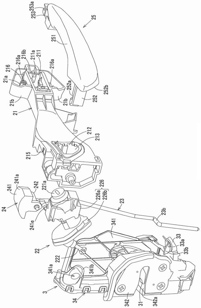
[0006] However, due to constraints on the interior space of the vehicle door, it is extremely difficult to insert the paddle portion of the cylinder lock for the vehicle door into the door lock rotor of the door latch mechanism while moving the door latch mechanism as described above (that is, to link the operation). difficult

Method used


Image

  • Door lock device for vehicle and installation method thereof
  • Door lock device for vehicle and installation method thereof
  • Door lock device for vehicle and installation method thereof

Examples


Deformed example 1

[0134] Figure 9 It is a perspective view showing a modified example of the paddle portion 222 of the above-mentioned embodiment. The paddle portion 222 of the above-mentioned embodiment is positioned in a direction inclined from the central axis T1 of the support portion 225 by the elastic member 222g provided in the connecting portion 222c, as shown in FIG. Figure 9 As shown, the paddle portion 222 of Modification 1 is biased in a direction inclined from the central axis T1 of the support portion 225 by the biasing member 222h provided on the outer peripheral surface of the paddle portion 222 .

[0135]More specifically, in Modification 1, the urging member 222h is, for example, a double coil spring, and includes two coil springs 222h1 and a substantially U-shaped restricting portion 222h2 formed by connecting one ends of the coil springs 222h1 to each other. , and the locking end 222h3 which is the free end of the two coil springs 222h1.

[0136] Furthermore, in Modifica...

Deformed example 2

[0146] Figure 10 is a perspective view showing another modified example of the paddle portion 222, Figure 11 It is a side view illustrating a method of mounting the vehicle door lock device 1 in another modified example of the paddle portion 222 .

[0147] In the above-mentioned embodiment, as the displacement relative to the far-near direction of the door lock rotor 32, the paddle portion 222 can rotate between the direction of the central axis T1 of the support portion 225 and a direction inclined relative to the central axis T1, However, in Modification 2, the paddle portion 222 is slidable relative to the support portion 225 in the insertion / extraction direction with respect to the door lock rotor 32 as the displacement in the far-near direction with respect to the door lock rotor 32 .

[0148] In more detail, as Figure 10 as well as Figure 11 As shown in (a), in Modification 2, the blade body 222a of the blade 222 is formed in a bottomed cylindrical shape (for exam...


PUM


Abstract

Provided is a door lock device for a vehicle that can easily separate the paddle portion of the cylinder lock for the door and the door lock rotor of the door latch portion when the door latch mechanism is attached to the door after the cylinder lock for the door is attached to the door. A door lock device for a vehicle linked by an action. The door lock device for a vehicle of the present invention includes: a door handle base, which is provided on a vehicle door, and is provided with a cylinder lock; The pluggable action link transmits the rotation of the lock cylinder to the door latch mechanism; and the support part supports the paddle part in a rotatable manner. The door latch mechanism has a door lock rotor for the paddle part to be pluggable. Inserted in such a way that the paddle portion is displaceably supported by the support portion in the far-near direction relative to the door lock rotor.

Description

technical field [0001] The present invention relates to a vehicle door lock device and an installation method thereof. Background technique [0002] In a conventional door lock device for a vehicle, a key insertion portion of a cylinder key for a door is arranged around a door handle on a main surface on the outside of a vehicle door. Therefore, after the door latch mechanism is attached to the door, the cylinder lock for the door can be attached to the door from the outside of the vehicle. As a result, the blade portion of the door cylinder lock can be easily inserted into the door lock rotor of the door latch mechanism (that is, the operation is linked) (see Patent Document 1). [0003] Patent Document 1: Japanese Patent Laid-Open No. 2011-026826 [0004] However, as described above, in the structure in which the key insertion portion of the door cylinder lock is disposed on the outside main surface of the door around the door handle (that is, the structure in which the ...

Claims


Application Information

Patent Timeline
Patent Type & Authority Patents(China)
IPC IPC(8): E05B85/10E05B85/00
CPCE05B85/10E05B85/00E05B79/02E05B79/12E05B17/041E05B85/06E05B79/18E05Y2900/531E05B77/36E05B85/16
Inventor 岩田真介森胁裕介吉冈浩司越智勋赤木伸哉
Owner MAZDA MOTOR CORP
Features
  • R&D
  • Intellectual Property
  • Life Sciences
  • Materials
  • Tech Scout
  • Unparalleled Data Quality
  • Higher Quality Content
  • 60% Fewer Hallucinations
Learn More