Supercharge Your Innovation With Domain-Expert AI Agents!

Method for determining maximum deflection of elasticity limited circular thin film under condition of large corner

A technology of maximum deflection and elastic limit, applied in the direction of using stable tension/pressure to test material strength, strength characteristics, instruments, etc., can solve problems such as error amplification

Active Publication Date: 2019-07-19
CHONGQING UNIV
View PDF4 Cites 3 Cited by
  • Summary
  • Abstract
  • Description
  • Claims
  • Application Information

AI Technical Summary

Problems solved by technology

However, under the action of lateral uniform load, many flexible films can easily produce a film corner greater than 20o, and sin20o=0.34202, tan20 o =0.36397, then the error of the small rotation angle assumption itself ((tan20 o -sin20o) / sin20o) has already exceeded 6%, and there are usually some error amplification factors in the derivation process of the analytical solution, so at this time, the influence of the small rotation angle assumption on the calculation accuracy of the analytical solution is far more than 6% error

Method used


Image

  • Method for determining maximum deflection of elasticity limited circular thin film under condition of large corner
  • Method for determining maximum deflection of elasticity limited circular thin film under condition of large corner
  • Method for determining maximum deflection of elasticity limited circular thin film under condition of large corner

Examples


Embodiment Construction

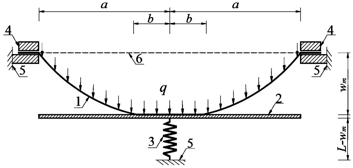
[0031] Combine below figure 1 The technical scheme of the present invention is described further:

[0032] Such as figure 1 As shown, Young’s modulus of elasticity E=7.84N / mm with a clamping device with inner radius a=50mm 2 , Poisson's ratio ν=0.47, thickness h=1mm, self-weight per unit area q 0 =7.64×10 -7 N / mm 2 The initial flat film is fixed and clamped, so as to form a circular film structure with a radius a=50mm, and a large enough uniform load q is applied to the circular film transversely, so that the circular film can produce axisymmetric deformation At the same time, a larger film corner can be produced, so that the maximum deflection of the axisymmetrically deformed circular film reaches w m , and the axisymmetrically deformed circular film pushes a rigid circular plate with a smooth surface, parallel to the plane where the original flat film is located, coaxial with the circular film, and radius a=50mm to move in parallel by w m , and the parallel moving rigi...


PUM


Abstract

The invention discloses a method for determining the maximum deflection of an elasticity limited circular thin film under the condition of a large corner. The method comprises the steps: an initiallyflat thin film with the Young's elastic modulus being E, the Poisson ratio being v, the thickness being h and the unit area self-weight being q0 is fixedly clamped through a clamping device with the inside radius being a, and thus a circular thin film structure with the radius being a and the periphery being fixedly clamped is formed; a large enough evenly-distributed load q is transversely applied to the circular thin film, and thus the circular thin film can generate the large thin film corner while generating axis symmetrical deformation, so that the maximum deflection of the circular thinfilm subjected to axis symmetrical deformation reaches wm; the circular thin film subjected to axis symmetrical deformation pushes a rigid circular plate provided with a smooth surface, parallel to the plane where the initially flat thin film is located, sharing the same axis with the circular thin film and having the radius of a to parallelly move by wm; the parallelly moving rigid circular platecompresses a spring with the original length being L and the stiffness factor being k by wm, and the radius of an interaction circular contact area between the circular thin film subjected to axis symmetrical deformation and the rigid circular plate is finally stabilized on b; and then after the self-weight of the rigid circular plate is ignored, based on static balance analysis of the axis symmetrical deformation problem of the circular thin film, the maximum deflection wm of the circular thin film subjected to axis symmetrical deformation can be determined through a measurement value of theload q.

Description

technical field [0001] The invention relates to a method for determining the maximum deflection of a circular film whose circumference is fixed and clamped under the action of transverse uniform load and whose deflection is limited by elasticity under the condition of a relatively large film corner. Background technique [0002] Axisymmetric deformation of circumferentially fixed clamped circular membranes with elastically limited deflection under uniform transverse loads has applications in many engineering fields, e.g. for the study of adhesion energy measurements of membrane / substrate systems, as well as for To develop various instruments and meters and various sensors. However, the existing analytical solutions to the axisymmetric deformation of circular membranes under uniform lateral loads are all obtained under the assumption that the membrane rotation angle θ is small, that is, the deformation of circular membranes under uniform lateral loads The film rotation angle...

Claims


Application Information

Patent Timeline
IPC IPC(8): G01N3/08G01N3/04G01B21/32G06F17/11
CPCG01B21/32G01N3/04G01N3/08G01N2203/0252G01N2203/0282G06F17/11
Inventor 孙俊贻李雪何晓婷李守振梅东郭莹
Owner CHONGQING UNIV
Features
  • R&D
  • Intellectual Property
  • Life Sciences
  • Materials
  • Tech Scout
  • Unparalleled Data Quality
  • Higher Quality Content
  • 60% Fewer Hallucinations
Learn More