Touch panel and touch panel device

A touch panel and area technology, applied in the direction of instruments, computing, electrical digital data processing, etc., can solve the problem of distinguishing between untouchable points and false touch points

Pending Publication Date: 2019-07-19
TIANMA JAPAN LTD +1
View PDF2 Cites 0 Cited by
  • Summary
  • Abstract
  • Description
  • Claims
  • Application Information

AI Technical Summary

Problems solved by technology

However, the inventor's research shows that the problem caused by thinning the projected capacitive touch panel is that in the case of multi-touch, real touch points cannot be distinguished from fake touch points

Method used


Image

  • Touch panel and touch panel device
  • Touch panel and touch panel device
  • Touch panel and touch panel device

Examples


Embodiment Construction

[0027] Hereinafter, embodiments will be described with reference to the accompanying drawings. The embodiments are merely examples for implementing the present invention, and do not limit the technical scope of the present invention. Elements common to the figures are denoted by the same reference numerals. The drawings may exaggerate the size and shape of elements for clarity of illustration.

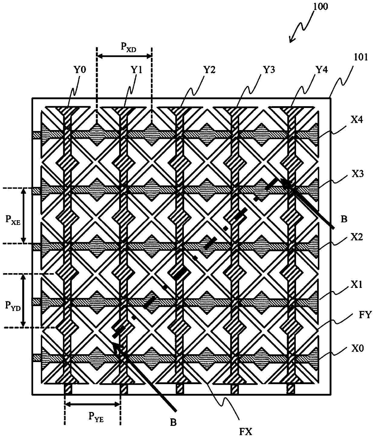
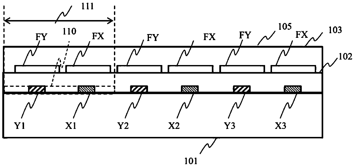
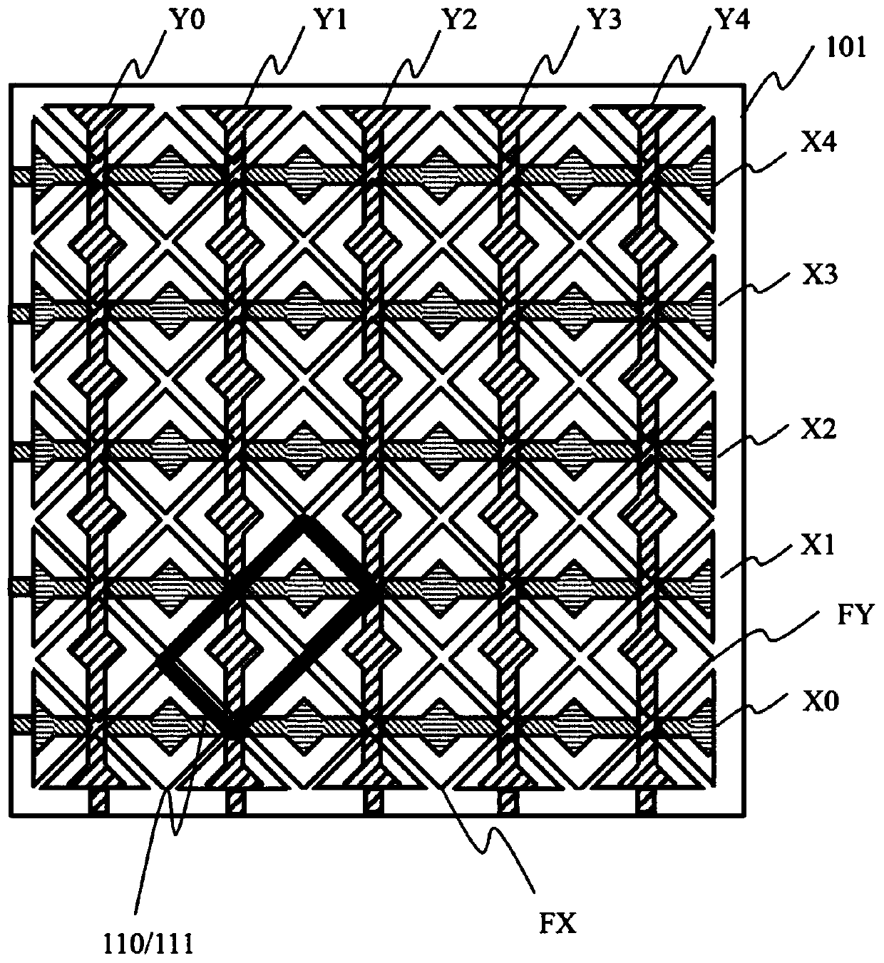
[0028] refer to Figure 1A , Figure 1B and Figure 1C , the structure of the touch panel (touchpad panel) 100 is described. Figure 1A and Figure 1C is a top view schematically showing the touch panel 100; Figure 1B schematically shows the Figure 1A The cross-sectional structure of the touch panel 100 cut by the line B-B in .

[0029] The touch panel 100 includes a support substrate 101 , and further includes X electrodes X0 to X4 and Y electrodes Y0 to Y4 disposed on the support substrate 101 . although Figure 1A The example in includes five X electrodes and five Y electrod...


PUM

PropertyMeasurementUnit
Thicknessaaaaaaaaaa

Abstract

A touch panel and a touch panel device are provided. The touch panel includes X electrodes and Y electrodes disposed on a support substrate in such a manner that each of the Y electrodes intersects the X electrodes, X floating electrodes laminated on a first insulating layer at places opposed to the X electrodes, Y floating electrodes laminated on the first insulating layer at places opposed to the Y electrodes, and a second insulating layer covering the X floating electrodes and the Y floating electrodes. The area of X electrodes is smaller than the area of X floating electrodes and the areaof Y electrodes is smaller than the area of Y floating electrodes in a unit lattice region of a lattice formed of the X electrodes and the Y electrodes. A mutual capacitance generated between an X electrode and a Y electrode decreases when a surface of the second insulating layer is touched by a pointer.

Description

technical field [0001] The present invention relates to a touch panel and a touch panel device. Background technique [0002] In recent years, with the popularity of smartphones and tablet terminals, touch panels have been widely recognized as user-friendly user interfaces. Touch panels are mounted on display modules of various electronic devices. [0003] For example, JP2013-167953A discloses a touch panel and a display device that obtains higher sensitivity without changing the wiring design of the touch panel. Specifically, the capacitive coupling type touch panel includes a plurality of parallel X electrodes extending along a first direction and a plurality of parallel Y electrodes extending along a second direction on one side of a transparent substrate, the Y electrodes crossing the X electrodes , and an insulator is interposed between the Y electrode and the X electrode, the capacitive coupling type touch panel includes floating electrodes made of transparent conduc...

Claims


Application Information

Patent Timeline
IPC IPC(8): G06F3/044
CPCG06F3/044G06F2203/04104G06F3/0446G06F3/04186G06F3/0443G06F3/0445G06F3/0448G06F3/03547G06F3/016G06F3/0416
Inventor 芳贺浩史杉本大辅
Owner TIANMA JAPAN LTD
Why Eureka
Try Eureka