Touch sensing device and method thereof

A technology of touch sensing and sensing array, which is applied in the direction of instruments, electrical digital data processing, input/output process of data processing, etc., and can solve problems such as long response time

Inactive Publication Date: 2012-05-16
SILICON INTEGRATED SYSTEMS
View PDF5 Cites 16 Cited by
  • Summary
  • Abstract
  • Description
  • Claims
  • Application Information

AI Technical Summary

Problems solved by technology

To scan a frame, thousands of measurements must

Method used


Image

  • Touch sensing device and method thereof
  • Touch sensing device and method thereof
  • Touch sensing device and method thereof

Examples


Embodiment Construction

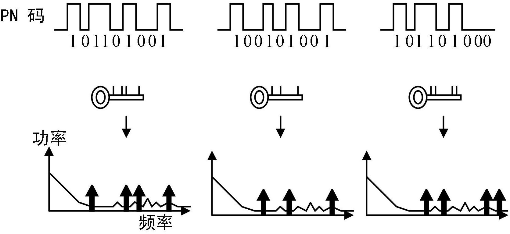
[0030]The present invention utilizes the property of orthogonal vectors. Assume that each vector of a vector group is Vi, where i=0, 1, ..., n. If the product of a vector with a different vector is 0 (that is, Vi × Vj = 0, where i ≠ j), and the product of a vector with itself is 1 (that is, Vi × Vj = 1, where i = j), then This is an orthogonal vector group. When V1 = (a1, b1, c1, d1) and V2 = (a2, b2, c2, d2), the product of V1 × V2 is equal to a1 × a2 + b1 × b2 + c1 × c2 + d1 ×d2. For example, if the vector group includes two vectors: V1 = (0, 0, 0, 1) and V2 = (0, 0, 1, 0), then V1 × V1 = 1, V1 × V2 = 0, and V2 × V2 = 1. Therefore, V1 and V2 are orthogonal.

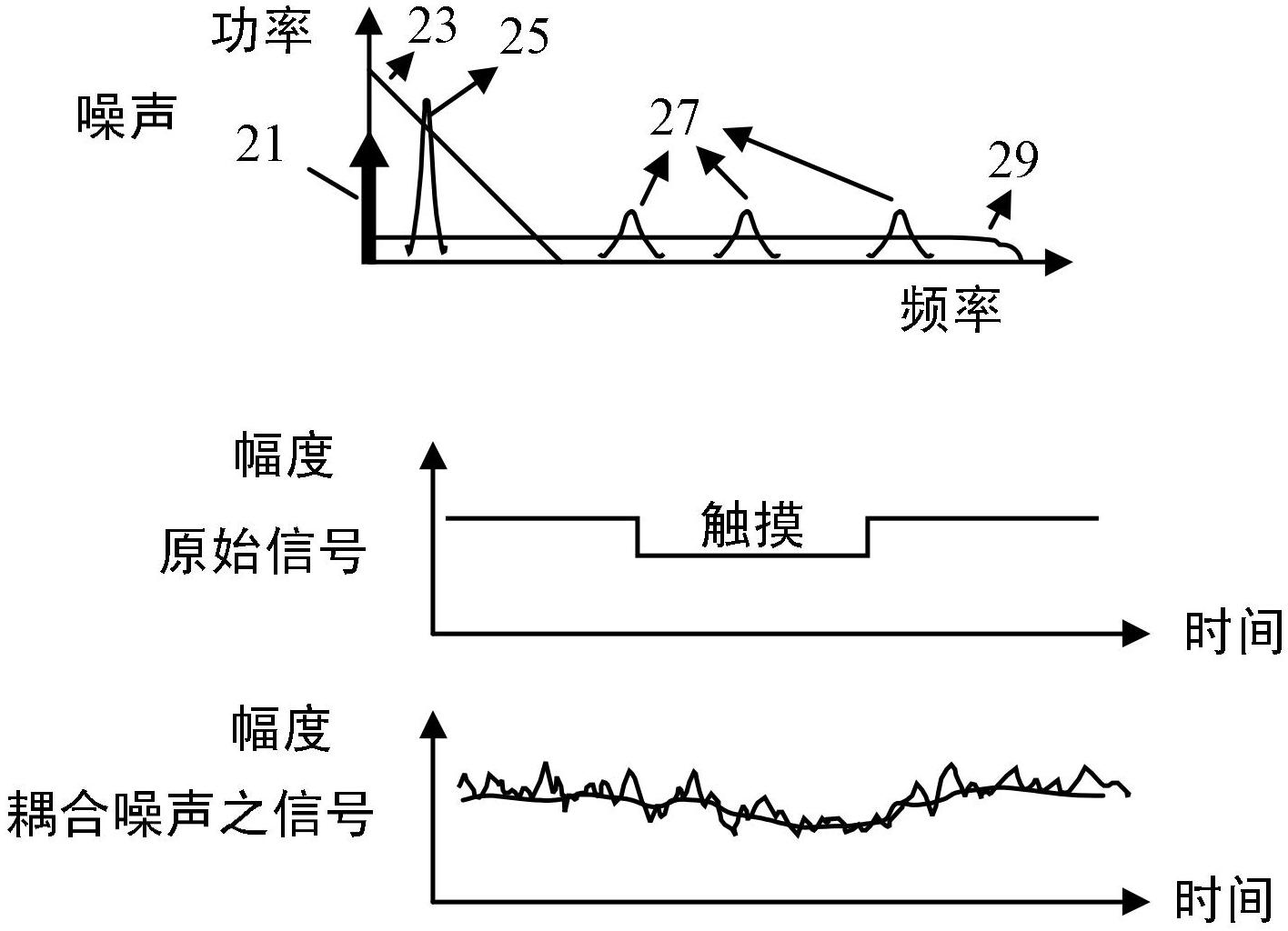
[0031] Any signal can be expressed as an orthogonal vector group, such as S = c1V1+c2V2+c3V3+…+cnVn, where c1, c2, …, cn are numbers. If the environmental noise is expressed as N = 100V1 + 50V2 + 20V3 + ​​10V4 + 2V5 + 4V6 + 10V7..., where each vector V1, V2, ... represents a specific band component. For a known si...


PUM


Abstract

The invention discloses a touch sensing device which utilizes the characteristics of orthogonal vectors. A driving signal is modulated by means of an RSS (Random Spread Spectrum) signal or a periodic wave, thus driving one column of a sensing array. The RSS signal or the periodic wave is used for extracting the touch signal of a node from sensed signals measured by one column of the sensing array. The node is the intersection point of the driven column and the measured column. When different RSS signals and/or different periodic waves are utilized to simultaneously drive a plurality of columns, the touch information of a plurality of points can be obtained simultaneously from the same sensed signal by extracting the touch information of the plurality of points by means of the RSS signals and/or the periodic waves, respectively; and the plurality of points are the intersection points of the driven columns and the measured column.

Description

technical field [0001] The present invention relates to touch sensing, and in particular to a low-noise touch sensing device capable of multi-touch sensing. Background technique [0002] A touch panel uses a sensing array to detect the location and intensity of a touch made by a finger, stylus, or the like. figure 1 It is a schematic diagram showing a general touch sensing device 1 (such as a touch panel) with a sensing array 10 . The sensing array 10 includes a group of longitudinal conductive tracks and a group of horizontal conductive tracks arranged in columns and rows in X-Y coordinates, or arranged in polar coordinates, with sensing elements (not shown) at each intersection. For example, sensing elements are typically implemented as resistors or capacitors. The control unit 12 transmits the driving signal to drive the row i of the sensing array 10 via the multiplexer 16 . The sensing signals of each column of the driven row i are sequentially or simultaneously detec...

Claims


Application Information

Patent Timeline
IPC IPC(8): G06F3/041
Inventor 吴鸿伟
Owner SILICON INTEGRATED SYSTEMS
Why Eureka
Try Eureka