Manufacturing device with holding tool and method for adjusting the total length of the curved edge of holding tool

A technology of manufacturing equipment, bending edges, applied in the field of manufacturing equipment, to achieve the effect of large adjustment path

Active Publication Date: 2020-10-30
TRUMPF MASCHEN AUSTRIA
View PDF10 Cites 0 Cited by
  • Summary
  • Abstract
  • Description
  • Claims
  • Application Information

AI Technical Summary

Problems solved by technology

This has the disadvantage that in order to adjust the clamping length / curved edge formed by the clamping tool set, the individual clamping tools between the two second clamping tool sections arranged on the outside have to be removed or added to the clamping tool set. first gripping tool section
This often requires extensive remodeling work

Method used


Image

  • Manufacturing device with holding tool and method for adjusting the total length of the curved edge of holding tool
  • Manufacturing device with holding tool and method for adjusting the total length of the curved edge of holding tool
  • Manufacturing device with holding tool and method for adjusting the total length of the curved edge of holding tool

Examples


Embodiment Construction

[0046] First of all, it is to be noted that in the different embodiments described, the same components have the same reference numerals / same component designations, wherein the disclosure contained throughout the specification can be similarly used with the same reference numerals / same artifact with the same component name. Furthermore, selected position indications in the description, such as at top, at bottom, at the side, relate directly to the described and depicted figures and in the event of a change in position, these position indications shall apply analogously to the new position.

[0047] In the following, the term "in particular / in particular" is to be understood as it may refer to possible more specific embodiments and more detailed descriptions of the subject matter or method steps, but does not necessarily represent a mandatory preference for the subject matter or method steps or methods. implementation.

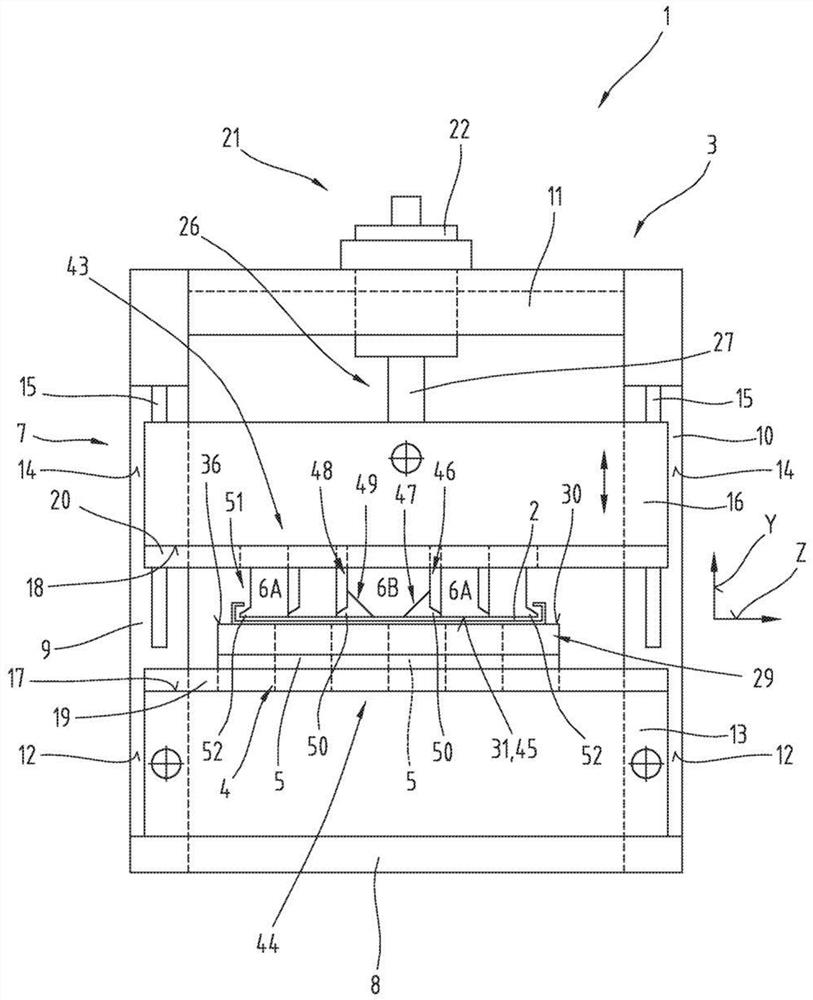
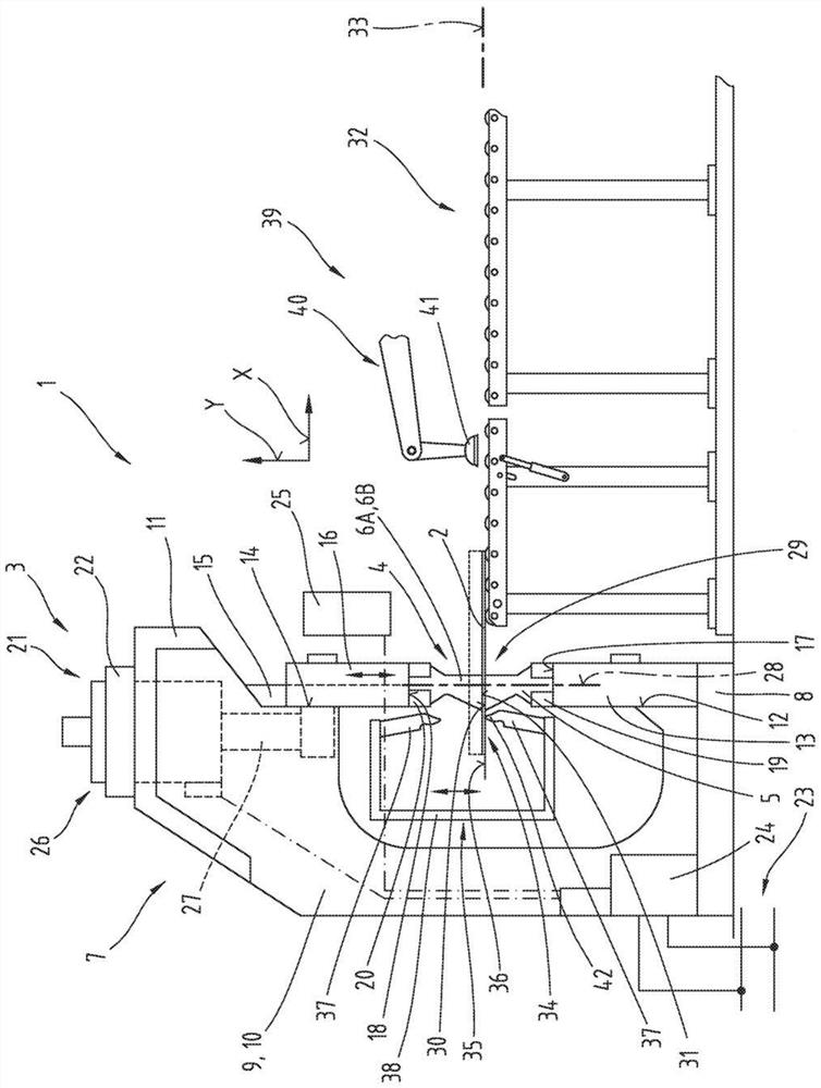
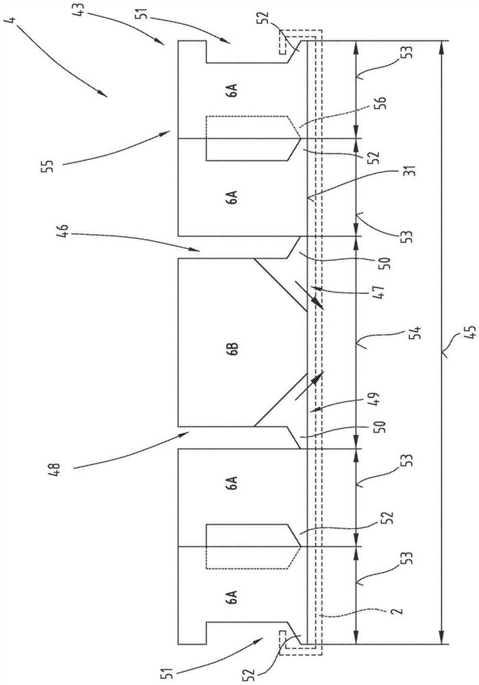
[0048] Figure 1 to Figure 5 The production plant 1 a...


PUM


Abstract

The invention relates to a manufacturing plant (1) for manufacturing workpieces (2) from sheet metal by forming them in a bending operation. The manufacturing equipment (1) comprises a bending machine (3) and a clamping tool (4) having at least one lower jaw (5) and an upper jaw set (43) comprising a plurality of first An upper jaw (6A) and a second upper jaw (6B). The second upper jaw (6B) has a jaw portion (47, 48) at each of its two end portions (46, 48) that can be moved from the working position to Move to the pulled out position. At least one upper jaw (6A) is provided on both sides of the second upper jaw (6B). The first upper jaw (6A) has a first corner (52) at each first end region (51) of the first upper jaw facing away from the second upper jaw (6B). The invention also relates to a method for adjusting the overall length of the curved edge (45) of the jaw set (43, 44) of such a manufacturing device (1).

Description

technical field [0001] The invention relates to a manufacturing plant for the manufacture of workpieces from sheet metal by forming in a bending operation, in particular by rotational bending or pendulum bending. However, the invention also relates to a method for adjusting the total length of the bent edges of a jaw set of a manufacturing plant for manufacturing workpieces from sheet metal by forming in a bending operation, in particular by rotary bending or pendulum bending. Background technique [0002] A commonly produced bending machine is known from DE 196 35 106 A1. The bending machine comprises a bending wall and first and second clamping cheeks for clamping a workpiece. One of the clamping cheeks comprises an interchangeably arranged first clamping tool section and a second clamping tool section of the clamping tool set. On both sides of the clamping tool group there is respectively a second clamping tool section comprising a separate part which is adjustable rela...

Claims


Application Information

Patent Timeline
Patent Type & Authority Patents(China)
IPC IPC(8): B21D5/04
CPCB21D5/047B21D5/04
Inventor 米夏埃尔·奥青格
Owner TRUMPF MASCHEN AUSTRIA
Why Eureka
Try Eureka