TOOL DRIVING UNIT, TURNING DEVICE AND TURNING METHOD, and application thereof

A driving unit and tool technology, applied in turning equipment, turning equipment, metal processing equipment, etc., can solve the problems of long production time, expensive, difficult to keep spheres and cylinders within tolerances, etc.

Pending Publication Date: 2021-04-30
光电科技光学机械有限责任公司
View PDF1 Cites 0 Cited by
  • Summary
  • Abstract
  • Description
  • Claims
  • Application Information

AI Technical Summary

Problems solved by technology

Prism machining is problematic even with known small tool radii, because especially in optical lenses and glass it is difficult to keep the surface quality of spheres and cylinders within tolerances in machining centers
Therefore, production times are long and it is expensive to produce high-quality faces in machining centers

Method used


Image

  • TOOL DRIVING UNIT, TURNING DEVICE AND TURNING METHOD, and application thereof
  • TOOL DRIVING UNIT, TURNING DEVICE AND TURNING METHOD, and application thereof
  • TOOL DRIVING UNIT, TURNING DEVICE AND TURNING METHOD, and application thereof

Examples


Embodiment Construction

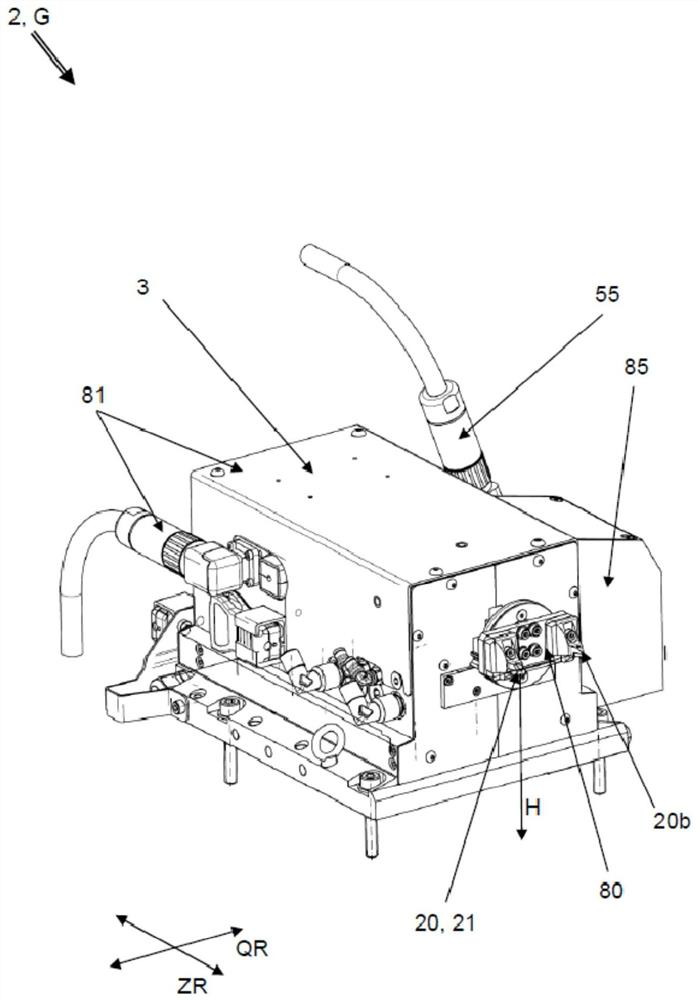
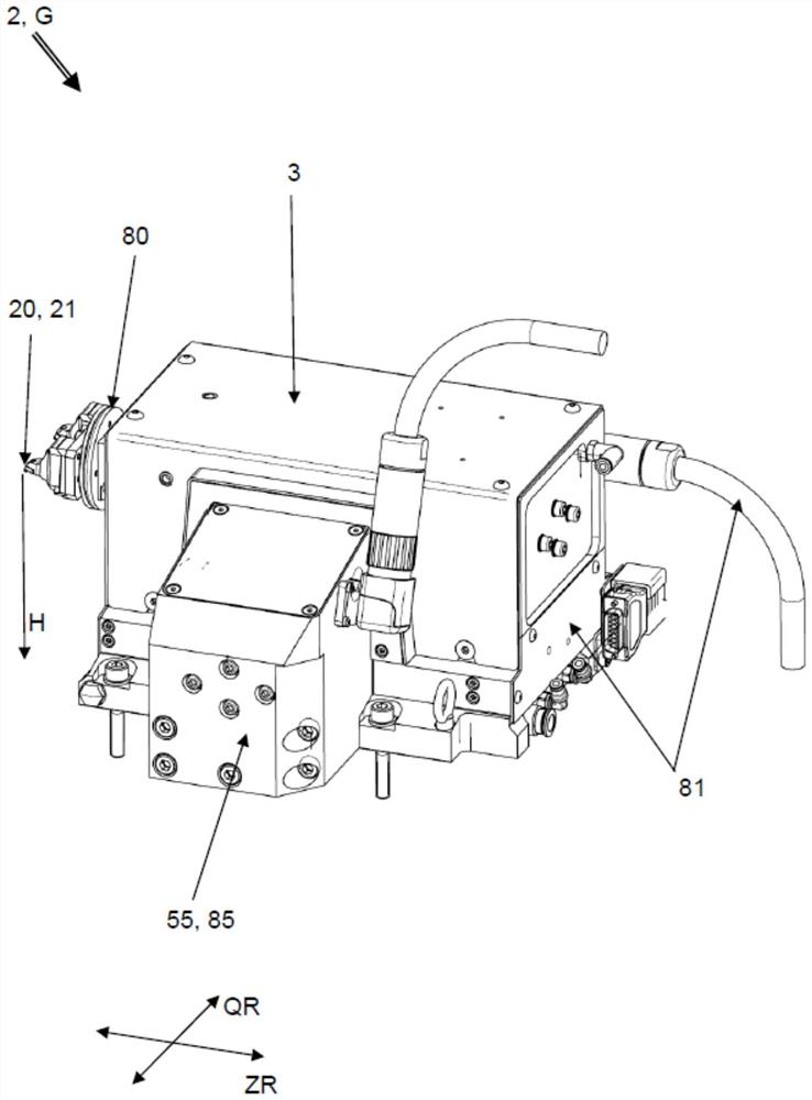
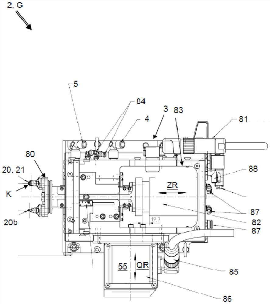
[0129] figure 1 A perspective view showing a tool drive unit 2 of a turning device for turning a workpiece (see Figure 5 ), the tool drive unit is formed as component G. exist figure 2 This component G is shown from different perspectives in . The same reference numbers therefore refer to the same components, because figure 1 and2 are described together. The components G have a common housing 3 . Protruding from one side of the housing 3 is a tool holder 80 in which the turning tool 20 with the defined cutting tool 21 is accommodated and the second turning tool 20b is accommodated additionally adjacent thereto. The cutter 21 can consist, for example, of natural diamond, synthetic diamond or ceramic, or have a CVD diamond layer (CVD=chemical vapor deposition) on a carrier substrate. The cutter 21 has a main cutting direction H in which the cutter 21 and the workpiece 100 are moved relative to each other for cutting. When using the tool drive unit 2 to process a lens bl...


PUM


Abstract

The invention provides a tool driving unit, a turning device and a turning method, and application thereof. The tool drive unit for the turning device for machining workpieces has a tool holder driven in a displaceable manner along an infeed direction by a first linear motor and driven in a pendular/displaceable manner in a direction transverse to the infeed direction by a second linear motor. Both linear motors have a moving coil/piezo element. The turning device has a main infeed drive, which produces a primary infeed movement of a turning tool in an infeed direction, and has a main transverse drive which produces a primary transverse movement in a transverse direction transversely to the infeed direction. The turning device has a secondary transverse drive whose movements are oriented in the same direction as the main transverse drive, wherein the turning tool and the axis of rotation can be moved towards one another and away from one another by the superimposition of primary and secondary transverse movements.

Description

technical field [0001] The invention relates to a tool drive unit according to the preamble of claim 1 , a turning device according to claim 7 , a front face for a workpiece driven about an imaginary axis of rotation by means of a turning tool according to claim 10 A method of performing machining and a turning device for carrying out the method according to claim 21 . Background technique [0002] The tool drive unit is used to automatically position the tool at a defined position on the machine so that the workpiece can be machined precisely. In addition, such tool drive units are present in turning machines in order to be able to position the turning tool with the cutter relative to the rotating workpiece. Then, according to the method, the turning tool is brought into engagement with the workpiece and the chips are removed from the workpiece by a rotational main movement of the workpiece. By moving the turning tool relative to the workpiece, the workpiece is machined i...

Claims


Application Information

Patent Timeline
Patent Type & Authority Applications(China)
IPC IPC(8): B23Q5/22B23B5/00B23B27/00B23B29/04
CPCB23Q5/22B23B5/00B23B27/00B23B29/04B23B2228/04B23B2226/18B23Q1/621B23Q1/34B23B2270/54B23B5/36B23B29/26B23Q1/58B23Q1/56B23B2210/02B23B2215/40B23Q5/02B24B13/00B23B1/00
Inventor R·曼德勒
Owner 光电科技光学机械有限责任公司
Why Eureka
Try Eureka