Uplink LBT method and device, medium and terminal
A technology of the same, beam direction, used in the field of communication
- Summary
- Abstract
- Description
- Claims
- Application Information
AI Technical Summary
Problems solved by technology
Method used
Image

Examples
Embodiment Construction
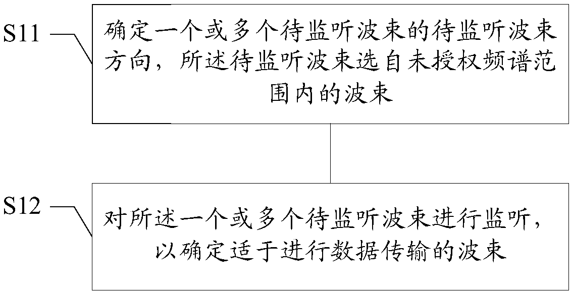
[0064] As mentioned above, NR-based unlicensed spectrum communication technology has become a new technology hotspot. Based on the new characteristics of NR, LBT technology needs to be changed accordingly. However, there is currently no beam direction based LBT technique in NR scenarios.
[0065] In the NR scenario, data transmission can be performed based on multiple beams, and the beams can be distinguished by the type and serial number of the RS carrying the beams. Different beams have different beam directions. The beam direction in the embodiment of the present invention may be carried by a channel state information reference signal (CSI Reference Signal, CSI-RS), a channel sounding signal (Sounding Reference Signal, SRS), a tracking reference signal (Tracking Reference Signal, TRS), a synchronization signal It is distinguished from the spatial configuration (spatial configuration) of any one or more of resources in a broadcast channel block (SS / PBCH Block, SSB) and a d...
PUM
 Abstract
Description
Claims
Application Information
 - R&D
- Intellectual Property
- Life Sciences
- Materials
- Tech Scout
- Unparalleled Data Quality
- Higher Quality Content
- 60% Fewer Hallucinations
Browse by: Latest US Patents, China's latest patents, Technical Efficacy Thesaurus, Application Domain, Technology Topic, Popular Technical Reports.
© 2025 PatSnap. All rights reserved.Legal|Privacy policy|Modern Slavery Act Transparency Statement|Sitemap|About US| Contact US: help@patsnap.com