SHANGHAI INST OF OPTICS & FINE MECHANICS CHINESE ACAD OF SCI
View PDF6 Cites 0 Cited by
Summary
Abstract
Description
Claims
Application Information
AI Technical Summary
This helps you quickly interpret patents by identifying the three key elements:
Problems solved by technology
Method used
Benefits of technology
Problems solved by technology
Especially prior art 3 is undoubtedly very important for the development of large-scale precision measurement technology, in which the width of all grid grooves is assumed to be uniform, on the order of hundreds of nanometers, but from the perspective of a single groove shape, it cannot Provide measurement benchmarks on the order of picometers
[0006] We can intuitively understand that although prior art 1, 2, or 3 all provide period measurement with picometer accuracy, they cannot provide the difference between different gratings
Method used
Image
Click on the blue label to locate the original text in one second.
Reading with bidirectional positioning of images and text.
Examples
Embodiment 1
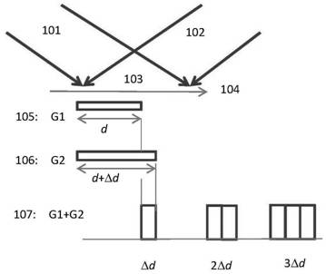
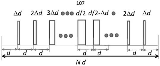
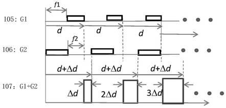
[0084] Assuming that the picometer comb is produced by two holographic exposures, the manufacturing process using holographic double-beam exposure is as follows: figure 1 As shown, the period of the grating 105 for the first exposure is d, and the period of the grating for the second exposure is d+Δd. If the second exposure and the development process are matched, the opening ratio of the second exposure grating is f1=f2= 0.5 (here the aperture ratio is defined as the ratio of the gate groove to the period), it will produce as figure 2 The picometer optical comb with continuously variable grating pitch shown in the figure, its change process in a complete picometer optical comb period N·d is as follows figure 2 shown.
[0085] Here, the aperture ratios f1 and f2 are related to the amount of secondary exposure, the degree of development, and the like. The specific numbers of f1 and f2 can be calibrated in advance by setting the relationship between exposure amount and devel...
Embodiment 2
[0088] The picometer comb may also have larger f1 and f2 caused by two exposures, such as Figure 4 As shown, at this time, there may be only one slot-shaped distribution in one cycle, for example, 411, 412, etc., and two distributions may also appear, for example, 42M and 41M appear in one cycle, which shows that both f1 and f2 In larger cases, there may be a frequency doubling effect of the picometer comb. Finally, there may be a situation where the groove width of 42N2 and 42N1 gradually increases.
Embodiment 3
[0090] It is also possible for the picometer comb to have small f1 and f2, such as Figure 5 shown. For example, f1
[0091] Of course, for the distribution of f1 and f2 in other situations, there are more possibilities.
[0092] Since we can accurately measure the periods of the first and second exposures, reaching the picometer level, through the second exposure technology and changing the period of the second exposure, by setting the difference between the grating periods during the two exposures , the precise groove shape distribution of the picometer optical comb can be obtained, wherein the width of each groove shape is relative to the groove shape of the adjacent period, and the differenc...
PUM
Abstract
A kind of manufacturing device and manufacturing method of pico optical comb and pico optical comb. Compared with the gate groove, there is a fixed difference, such as Δd, and the difference Δd can be from picometer to nanometer. The pico-comb of the present invention will provide a benchmark for pico-meter measurement. The pico optical comb will generate a diffractive light field distribution different from the traditional grating, which will bring new diffraction effects, realize new diffractive optical functions, and provide tools such as pico lithography, pico measurement, and pico imaging, so , picometer optical combs will play an important role in many fields such as semiconductor lithography, life sciences, and the interaction between light and matter at the picometer scale.
Description
technical field [0001] The present invention relates to a kind of special grating, especially a kind of manufacturing device and method of picometer optical comb and picometer optical comb. , picometer microscopic imaging and many other aspects. Background technique [0002] Picometer-scale measurement is at the forefront of current science and technology. Advanced semiconductor lithography technology can already process nodes of several nanometers, which requires higher-precision measurement technology to calibrate it, that is, optical technology of tens or hundreds of picometers is required for measurement. Therefore, the development of advanced The picometer-scale optical measurement technology is the key to solve the picometer measurement today. [0003] As far as we know, because the picometer scale is too small, there is no traceable picometer measurement benchmark with a large moving range. If a laser interferometer is used, because the laser interferometer has inh...
Claims
Application Information
Patent Timeline
Application Date:The date an application was filed.
Publication Date:The date a patent or application was officially published.
First Publication Date:The earliest publication date of a patent with the same application number.
Issue Date:Publication date of the patent grant document.
PCT Entry Date:The Entry date of PCT National Phase.
Estimated Expiry Date:The statutory expiry date of a patent right according to the Patent Law, and it is the longest term of protection that the patent right can achieve without the termination of the patent right due to other reasons(Term extension factor has been taken into account ).
Invalid Date:Actual expiry date is based on effective date or publication date of legal transaction data of invalid patent.
