Supercharge Your Innovation With Domain-Expert AI Agents!

Picometer optical comb, manufacturing device and manufacturing method of picometer optical comb

A technology for manufacturing devices and picometers, which is applied in special grating fields, and can solve problems such as the inability to provide different grating differences and the inability to provide picometer-level measurement benchmarks.

Active Publication Date: 2019-08-30
SHANGHAI INST OF OPTICS & FINE MECHANICS CHINESE ACAD OF SCI
View PDF6 Cites 7 Cited by
  • Summary
  • Abstract
  • Description
  • Claims
  • Application Information

AI Technical Summary

Problems solved by technology

Especially prior art 3 is undoubtedly very important for the development of large-scale precision measurement technology, in which the width of all grid grooves is assumed to be uniform, on the order of hundreds of nanometers, but from the perspective of a single groove shape, it cannot Provide measurement benchmarks on the order of picometers
[0006] We can intuitively understand that although prior art 1, 2, or 3 all provide period measurement with picometer accuracy, they cannot provide the difference between different gratings

Method used


Image

  • Picometer optical comb, manufacturing device and manufacturing method of picometer optical comb
  • Picometer optical comb, manufacturing device and manufacturing method of picometer optical comb
  • Picometer optical comb, manufacturing device and manufacturing method of picometer optical comb

Examples


Embodiment 1

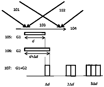
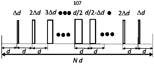
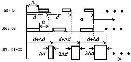
[0084] Assuming that the picometer comb is produced by two holographic exposures, the manufacturing process using holographic double-beam exposure is as follows: figure 1 As shown, the period of the grating 105 for the first exposure is d, and the period of the grating for the second exposure is d+Δd. If the second exposure and the development process are matched, the opening ratio of the second exposure grating is f1=f2= 0.5 (here the aperture ratio is defined as the ratio of the gate groove to the period), it will produce as figure 2 The picometer optical comb with continuously variable grating pitch shown in the figure, its change process in a complete picometer optical comb period N·d is as follows figure 2 shown.

[0085] Here, the aperture ratios f1 and f2 are related to the amount of secondary exposure, the degree of development, and the like. The specific numbers of f1 and f2 can be calibrated in advance by setting the relationship between exposure amount and devel...

Embodiment 2

[0088] The picometer comb may also have larger f1 and f2 caused by two exposures, such as Figure 4 As shown, at this time, there may be only one slot-shaped distribution in one cycle, for example, 411, 412, etc., and two distributions may also appear, for example, 42M and 41M appear in one cycle, which shows that both f1 and f2 In larger cases, there may be a frequency doubling effect of the picometer comb. Finally, there may be a situation where the groove width of 42N2 and 42N1 gradually increases.

Embodiment 3

[0090] It is also possible for the picometer comb to have small f1 and f2, such as Figure 5 shown. For example, f1

[0091] Of course, for the distribution of f1 and f2 in other situations, there are more possibilities.

[0092] Since we can accurately measure the periods of the first and second exposures, reaching the picometer level, through the second exposure technology and changing the period of the second exposure, by setting the difference between the grating periods during the two exposures , the precise groove shape distribution of the picometer optical comb can be obtained, wherein the width of each groove shape is relative to the groove shape of the adjacent period, and the differenc...


PUM


Abstract

The invention discloses a picometer optical comb, and a manufacturing device and a manufacturing method of the picometer optical comb. The picometer optical comb is a special optical grating of whichthe slot widths of adjacent grid lines are continuously variable, and is characterized in that the widths of each grid slot and the adjacent grid slot are differed by a fixed difference value, such as[delta]d that can be from a picometer level to a nanometer level. The picometer optical comb provided by the invention provides a datum for picometer measurement. The picometer optical comb generatesdiffractive light field distribution different from the traditional optical grating, so that a new diffraction effect is brought in, a new diffraction optical function is achieved, and tools such aspicometer photoetching, picometer measurement and picometer imaging are provided, and thus the picometer optical comb will play an important role in multiple fields of semiconductor photoetching, bioscience, light-matter interaction in the picometer level.

Description

technical field [0001] The present invention relates to a kind of special grating, especially a kind of manufacturing device and method of picometer optical comb and picometer optical comb. , picometer microscopic imaging and many other aspects. Background technique [0002] Picometer-scale measurement is at the forefront of current science and technology. Advanced semiconductor lithography technology can already process nodes of several nanometers, which requires higher-precision measurement technology to calibrate it, that is, optical technology of tens or hundreds of picometers is required for measurement. Therefore, the development of advanced The picometer-scale optical measurement technology is the key to solve the picometer measurement today. [0003] As far as we know, because the picometer scale is too small, there is no traceable picometer measurement benchmark with a large moving range. If a laser interferometer is used, because the laser interferometer has inh...

Claims


Application Information

Patent Timeline
Patent Type & Authority Applications(China)
IPC IPC(8): G02B5/18G03F7/20
CPCG02B5/1857G03F7/2022G02F1/21G03F7/0005G03F7/2053G03F7/70466G02B5/18
Inventor 周常河
Owner SHANGHAI INST OF OPTICS & FINE MECHANICS CHINESE ACAD OF SCI
Features
  • R&D
  • Intellectual Property
  • Life Sciences
  • Materials
  • Tech Scout
  • Unparalleled Data Quality
  • Higher Quality Content
  • 60% Fewer Hallucinations
Learn More