A suction type cylindrical foundation

A cylindrical foundation and suction technology, which is applied in infrastructure engineering, construction, etc., can solve problems such as difficulty in realizing automatic penetration, reducing foundation load capacity, and affecting foundation stability, so as to increase effective load capacity and improve soil penetration capacity , Enhance the effect of applicable ability

Active Publication Date: 2021-08-06
TAIZHOU XINGDAO MACHINERY MFG
View PDF0 Cites 0 Cited by
  • Summary
  • Abstract
  • Description
  • Claims
  • Application Information

AI Technical Summary

Problems solved by technology

[0003] see figure 2 , in actual use, the suction cylindrical foundation is mainly affected by the joint action of the vertical pull-out load brought by itself and its upper load and the horizontal load brought by the waves. Under long-term action, the strength of the foundation soil will change , especially the foundation soil near the cylinder foot will produce large shear damage, which will reduce the load capacity of the foundation. Under the action of horizontal load, the side of the cylinder body in the same direction as the load will passively squeeze the foundation soil on this side, However, the direction of the waves is always the same for a period of time, and the long-term unidirectional horizontal load will cause the cylinder to tilt and affect the stability of the foundation.
[0004] In some sea areas with hard soil, it is often difficult to achieve automatic penetration. At this time, divers need to enter the interior of the cylinder through the manhole at the upper end of the cylinder, and use jet mixing equipment to liquefy the hard soil or manually excavate to continue pumping and penetration. The construction is relatively difficult. cumbersome

Method used


Image

  • A suction type cylindrical foundation
  • A suction type cylindrical foundation
  • A suction type cylindrical foundation

Examples


Embodiment Construction

[0023] The following will clearly and completely describe the technical solutions in the embodiments of the present invention with reference to the accompanying drawings in the embodiments of the present invention. Obviously, the described embodiments are only some, not all, embodiments of the present invention. Based on the embodiments of the present invention, all other embodiments obtained by persons of ordinary skill in the art without making creative efforts belong to the protection scope of the present invention.

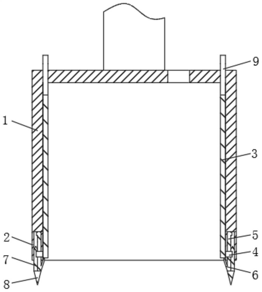
[0024] see Figure 3-8 , a suction-type cylindrical foundation, including a cylinder body 1, an auxiliary cylinder 2 is provided at the lower end of the cylinder body 1, and the auxiliary cylinder 2 is a part of the cylinder body 1, and several cavities are provided inside to accommodate functional parts, and the cylinder body 1 The inner wall is provided with movable ribs 3, and the auxiliary cylinder 2 and the cylinder body 1 can slide relative to each other...


PUM


Abstract

The invention relates to the technical field of marine engineering equipment, and discloses a suction cylindrical foundation, which includes a cylinder body, an auxiliary cylinder is provided at the lower end of the cylinder body, movable ribs are provided on the inner wall of the cylinder body, and the auxiliary cylinder A connecting rod is provided at a position corresponding to the movable rib. The tips of the inner fixing claws, outer fixing claws and bottom fixing claws are obliquely inserted into the foundation soil to disperse the uneven load and expand the force between the foundation soil and the foundation soil, so that the strength of the foundation soil can still maintain the cylinder body. It is stable and greatly increases the effective load capacity of the suction cylindrical foundation. Secondly, the bottom fixing claws evenly distributed at the bottom of the auxiliary cylinder have strong puncture ability, which improves the soil penetration capacity of the suction cylindrical foundation and enhances the The ability to adapt to the strength of the submarine foundation reduces the need for manual excavation by divers. At the same time, one side can be properly loosened in advance to ensure the uniform speed of its entry into the soil and ensure its vertical entry into the soil.

Description

technical field [0001] The invention relates to the technical field of marine engineering, in particular to a suction type cylindrical foundation. Background technique [0002] see figure 1 , the suction type cylindrical foundation is a fixed foundation applied to the underwater part of marine buildings. It is a cylinder with an open bottom and a closed top. Ribs are provided on the cylinder wall and the top of the barrel to ensure the strength of the cylinder. When installing, use a submersible pump to extract The liquid in the barrel creates a pressure difference between the inside and outside of the barrel, and presses the barrel-shaped foundation into the ground. [0003] see figure 2 , in actual use, the suction cylindrical foundation is mainly affected by the joint action of the vertical pull-out load brought by itself and its upper load and the horizontal load brought by the waves. Under long-term action, the strength of the foundation soil will change , especiall...

Claims


Application Information

Patent Timeline
Patent Type & Authority Patents(China)
IPC IPC(8): E02D27/24E02D27/52
CPCE02D27/24
Inventor 卢兴德
Owner TAIZHOU XINGDAO MACHINERY MFG
Why Eureka
Try Eureka