Straw filament rubbing and compacting field returning machine

A technology of straw and silk rollers, which is applied in the field of straw rubbing and densification returning machines, can solve the problems of insignificant organic matter content, inability of seeds to be in close contact with the soil, and slow decomposition of straw, so as to improve economic efficiency and long-term Sustainability of returning to the field, decomposition speed and nutrient release, and the effect of improving the distribution of organic matter

Pending Publication Date: 2019-09-20
JILIN UNIV
View PDF12 Cites 0 Cited by
  • Summary
  • Abstract
  • Description
  • Claims
  • Application Information

AI Technical Summary

Problems solved by technology

The existing straw returning machines mainly crush the straw and cover it on the ground surface, or bury it shallowly in the soil. Covering and returning the field can reduce the evaporation of soil water, but the straw decomposes slowly, which is easy to cause disease, and also delays the growth of crops
Shallow burial and returning to the field can easily cause too large soil voids, resulting in poor passability for subsequent sowing operations, and the seeds cannot be in close contact with the soil, affecting seed germination and other problems
Moreover, after the straws distributed on the soil surface decompose, the organic matter mainly exists on the soil surface, which has no obvious effect on the organic matter content of the entire plow layer soil, especially not conducive to the elimination of pests and weeds.

Method used


Image

  • Straw filament rubbing and compacting field returning machine
  • Straw filament rubbing and compacting field returning machine
  • Straw filament rubbing and compacting field returning machine

Examples


Embodiment Construction

[0069] The present invention will be further described in detail below in conjunction with the accompanying drawings, so that those skilled in the art can implement it with reference to the description.

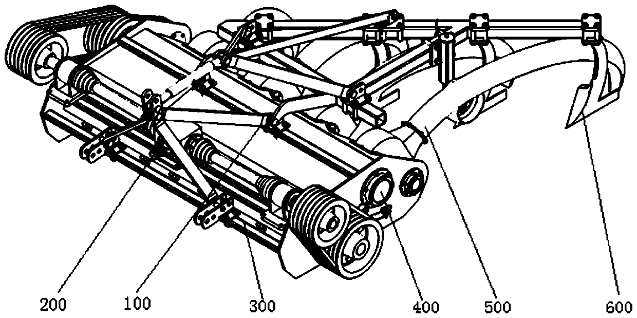
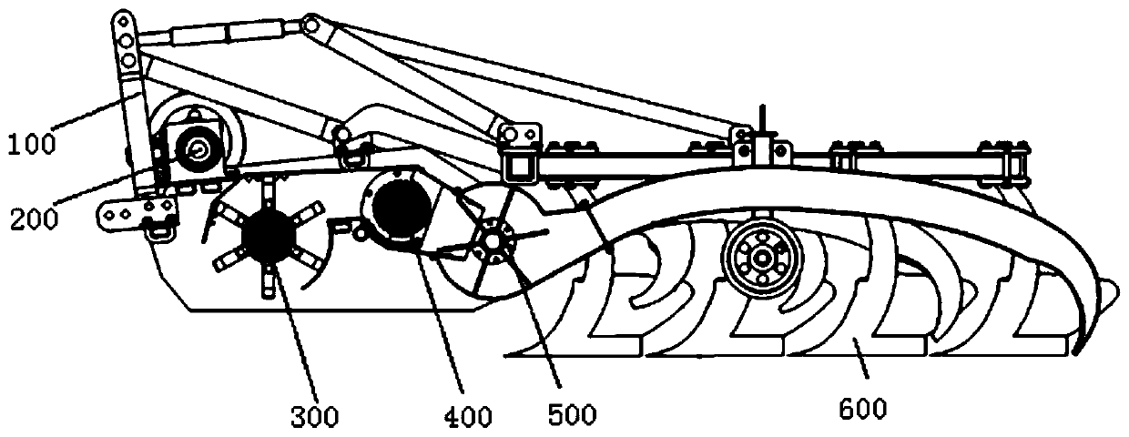
[0070] Such as Figure 1-2 As shown, the present invention provides a straw kneading and densifying returning machine, which mainly includes: a straw kneading and densifying machine housing 100, a power transmission device 200, a picking and shredding device 300, and a kneading and thinning device 400. Throwing and lifting conveying device 500, earth-digging and burying densification device 600.

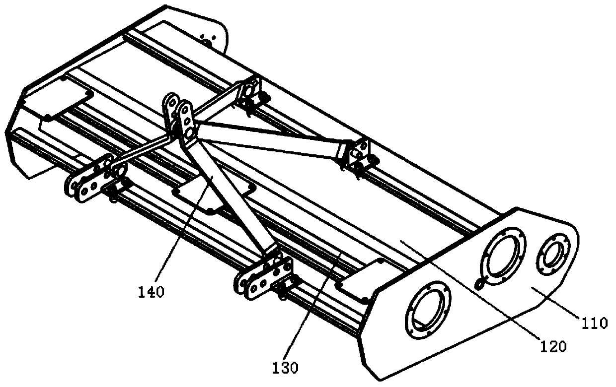
[0071] Such as image 3 As shown, the casing 100 of the straw rubbing and densifying machine includes: a side plate 110 , a steel plate 120 , a beam 130 , and a three-point suspension rod 140 . The casing 100 of the straw kneading and silk-densifying machine is welded by two side plates 120, plate-shaped steel 120 and beam 130, and the three-point suspension rod 140 is hinged to t...


PUM


Abstract

The invention discloses a straw filament rubbing and compacting field returning machine. The straw filament rubbing and compacting field returning machine comprises a shell, a picking and shredding device, a filament rubbing roller, a filament rubbing concave plate, a throwing and raising draught fan, multiple moldboard plows and multiple flow guide pipes; the shell comprises two side plates and multiple transverse beams; the picking and shredding device is installed on the shell; the two ends of the filament rubbing roller are rotatably supported on the two side plates respectively; the two ends of the filament rubbing concave plate are connected to the two side plates respectively; the concave face side of the filament rubbing concave plate faces the filament rubbing roller; the two ends of the throwing and raising draught fan are installed on the two side plates respectively, and a draught fan hood body is arranged at the outer side of the throwing and raising draught fan; the moldboard plows are suspended on the shell through a plow frame; the moldboard plows are equidistantly arranged at one side of the throwing and raising draught fan, and the distances between the moldboard plows and the throwing and raising draught fan are increased in sequence from one end of the draught fan to the other end of the draught fan; the flow guide pipes correspond to the moldboard plows one to one; after straw is shredded by the picking and shredding device, the straw passes through a filament rubbing gap, the draught fan hood body and the flow guide pipes in sequence, then falls into furrows formed by furrowing of the moldboard plows, and is then covered with soil blocks turned over by the adjacent moldboard plows.

Description

technical field [0001] The invention belongs to the technical field of agricultural engineering machinery, and in particular relates to a straw rubbing and silking densification returning machine. Background technique [0002] Applying straw to soil can supplement soil organic matter, increase soil microbial activity, enhance soil fertilizer supply capacity, and improve soil structure and physical and chemical properties. Straw returning is not only an irreplaceable main channel for straw utilization, but also a need to increase soil organic matter to protect soil fertility and achieve sustainable agricultural development. The existing modes of straw returning to the field are mostly crushed and then directly turned over and covered with straw, which takes a long time for straw returning to the field to decompose, especially in the alpine region, which has become the main practice of straw returning to the promotion of regional production. obstacle. The existing straw retu...

Claims


Application Information

Patent Timeline
Patent Type & Authority Applications(China)
IPC IPC(8): A01D82/00A01F29/00A01F29/09
CPCA01F29/005A01F29/09A01D82/00
Inventor 张强董瑞方旭文张莉于路路张劲松李大伟隋媛媛
Owner JILIN UNIV
Why Eureka
Try Eureka