
The fuel cell

A fuel cell and electrolyte membrane technology, applied in fuel cells, fuel cell parts, battery electrodes, etc., can solve the problems of fuel cell power generation performance degradation, insufficient supply, etc., and achieve the effect of suppressing power generation performance degradation

Active Publication Date: 2022-08-09
TOYOTA JIDOSHA KK
View PDF12 Cites 0 Cited by
  • Summary
  • Abstract
  • Description
  • Claims
  • Application Information

AI Technical Summary

Problems solved by technology

During such an interval, the reaction gas may not be sufficiently supplied to the catalyst layer, and the power generation performance of the fuel cell may degrade

Method used


Image

  • The fuel cell
  • The fuel cell
  • The fuel cell

Examples


Embodiment Construction

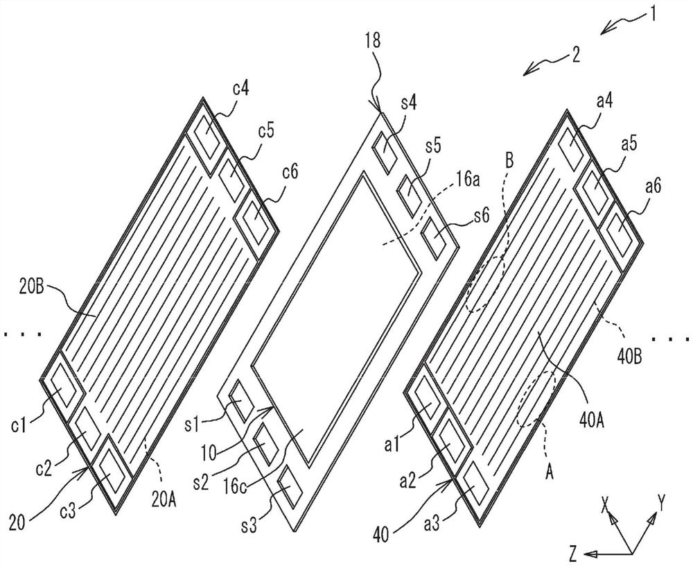
[0025] figure 1 It is an exploded perspective view of the unit cell 2 of the fuel cell 1 . The fuel cell 1 is constructed by stacking the unit cells 2 . figure 1 Only one unit cell 2 is shown and the other unit cells are omitted. unit cell 2 in figure 1 Stacked with other unit cells in the Z direction shown in . The unit cells 2 have a substantially rectangular shape. The longitudinal direction and the short direction of the unit cell 2 correspond to the figure 1 The Y and X directions shown in .

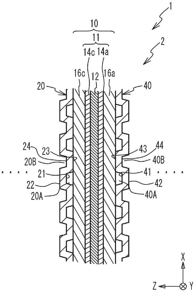
[0026] The fuel cell 1 is a solid polymer type fuel cell that generates electric power using a fuel gas (eg, hydrogen gas) and an oxidant gas (eg, oxygen gas) as reaction gases. The unit cell 2 includes: a membrane electrode gas diffusion layer assembly (MEGA) 10 ; a support frame 18 that supports the MEGA 10 ; a cathode separator 20 and an anode separator 40 (hereinafter, referred to as a separator) that connect the MEGA 10 sandwiched. The MEGA 10 has a cathode gas diffusio...


PUM


Abstract

A fuel cell includes: an electrolyte membrane; a first catalyst layer and a second catalyst layer formed on first and second surfaces of the electrolyte membrane, respectively; and a separator arranged with respect to the first catalyst layer In contrast to electrolyte membranes.

Description

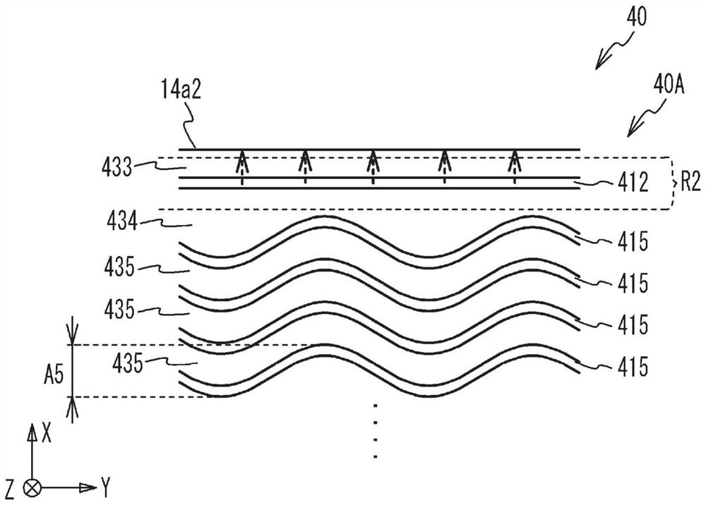
technical field [0001] The present invention relates to fuel cells. Background technique [0002] The separator of the fuel cell is formed with flow path grooves through which the reaction gas flowing between the separator and the catalyst layer formed on the electrolyte membrane flows. A part of the reaction gas flowing through the flow path grooves is supplied to the catalyst layer, so that a power generation reaction occurs. For example, in Japanese Unexamined Patent Application Publication No. 2006-147466, the separator is formed with wavy grooves as flow path grooves. [0003] For example, in Japanese Unexamined Patent Application Publication No. 2006-147466, a wavy groove is formed in a wavy shape having a predetermined amplitude, and the edge of the catalyst layer is formed in a substantially straight line. There is a large separation between the wavy grooves closest to the edge of the catalyst layer and the edge of the catalyst layer. In such an interval, the reac...

Claims


Application Information

Patent Timeline
Patent Type & Authority Patents(China)
IPC IPC(8): H01M8/1006H01M8/026H01M8/0258
CPCH01M8/1006H01M8/0258H01M8/026H01M2008/1095Y02E60/50H01M8/0267H01M8/1004H01M8/04029H01M8/2457H01M8/241H01M4/8807H01M8/04089
Inventor 野野山顺朗绀野周重伊藤雅之
Owner TOYOTA JIDOSHA KK
Learn More