Supercharge Your Innovation With Domain-Expert AI Agents!

A quick access system for logistics warehousing

A fast access and logistics technology, applied to storage devices, applications, household appliances, etc., can solve the problems of manpower consumption, inconvenient handling of goods, etc., and achieve the effect of flexible use

Active Publication Date: 2021-11-16
深圳圆融汇通跨境电商物流股份有限公司
View PDF0 Cites 0 Cited by
  • Summary
  • Abstract
  • Description
  • Claims
  • Application Information

AI Technical Summary

Problems solved by technology

[0002] With the development of logistics to supply chain management, companies are increasingly emphasizing the unique role of warehousing as a resource provider in the supply chain. Warehouses are no longer just warehouses for storing goods. The transformation of the center focuses more on the speed of item turnover, but the storage and retrieval in traditional technology is usually stacked by manual picking, which consumes manpower on the one hand, especially for the goods on the inner side.

Method used


Image

  • A quick access system for logistics warehousing
  • A quick access system for logistics warehousing
  • A quick access system for logistics warehousing

Examples


Embodiment 1

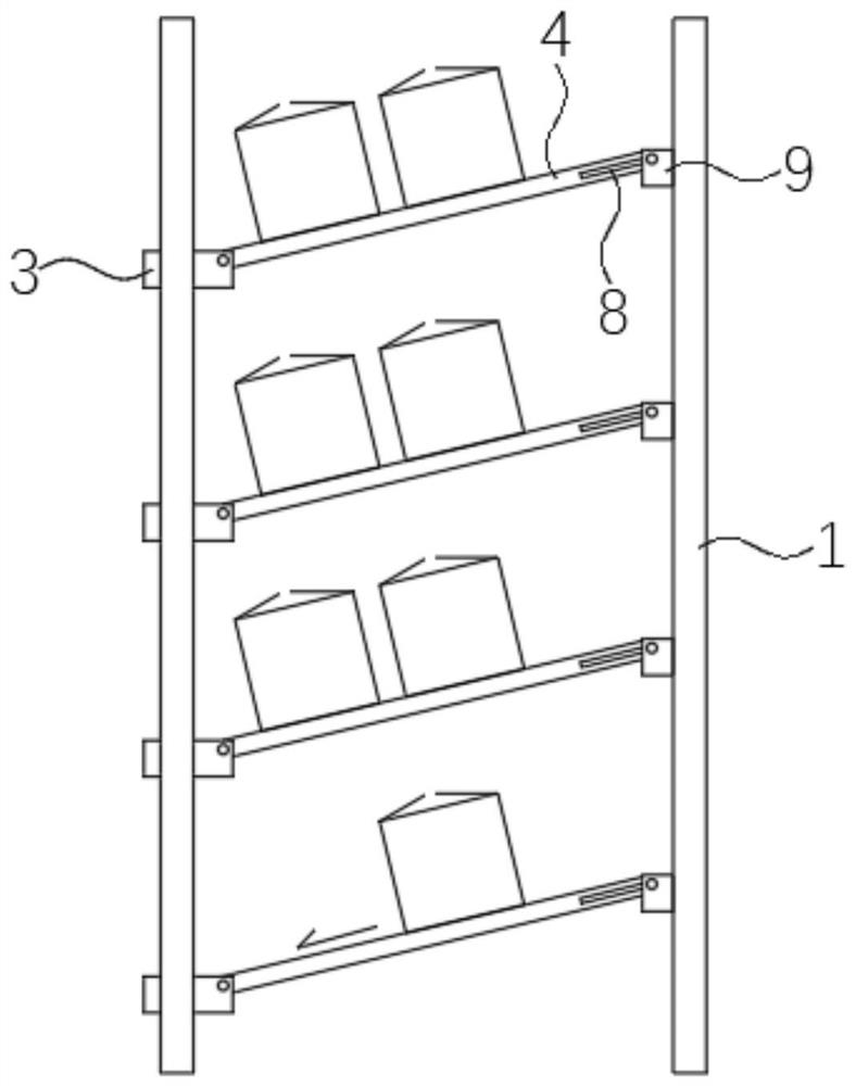
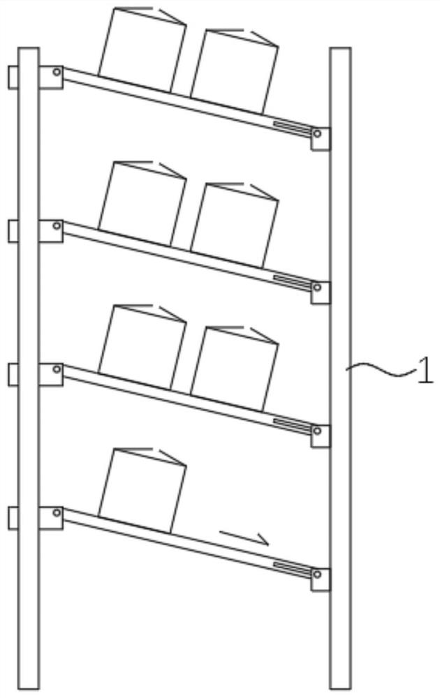
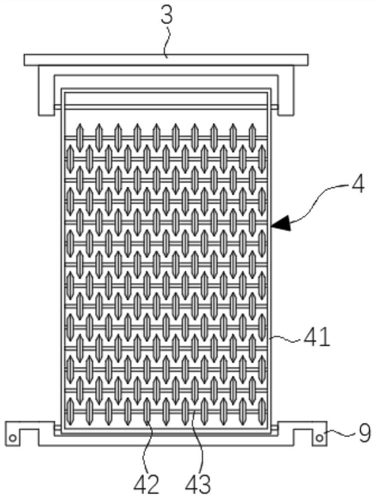
[0027] refer to Figure 1 to Figure 4 The inner side wall of the bracket 1 is fixedly connected with a plurality of first connecting plates 3 equidistantly from top to bottom, and each first connecting plate 3 is rotatably connected with a support plate 4, and the side of the support plate 4 away from the support 1 is rotatably connected with a The second connecting plate 9 is slidably connected to the support 1, and the two ends of the support 1 are equipped with a vertical lifting mechanism.

[0028] refer to Figure 4 The lifting mechanism includes a lead screw 6 and a reduction motor 7. The reduction motor 7 can use a planetary gear reduction motor, etc., or an external reducer such as a stepping motor or a servo motor. The two sides of the support 1 are symmetrically provided with vertical slides. Slot 2, leading screw 6 is vertically arranged in the chute 2, the leading screw 6 on both sides rotates synchronously through the transmission mechanism, the bottom end of the...

Embodiment 2

[0039] refer to Figure 5 with Image 6 , The difference between Embodiment 2 and Embodiment 1 lies in the difference of the lifting mechanism. In this embodiment, each supporting plate 4 is provided with a separate lifting mechanism, so as to control the independent movement of each layer of supporting plates, and the use is more flexible.

[0040] The elevating mechanism includes a weight block 11, an overturning frame 12, a fixed frame 13, a cylinder 14 and a cross bar 16, and the specific connection methods are as follows:

[0041] The overturning frame 12 is rotatably connected to the fixed frame 13, one side of the overturning frame 12 is fixedly connected with a cross bar 16, the other side of the overturning frame 12 is fixedly connected with a weight block 11, and one end of the overturning frame 12 is connected with a lever for driving its lever movement. Cylinder 14.

[0042] Both ends of the support plate 4 are fixedly connected with a hook-shaped spacer 15 , and...


PUM


Abstract

The invention discloses a quick access system for logistics storage, which relates to the technical field of storage and retrieval equipment. Both the first connecting plates are rotatably connected with a supporting plate, and the side of the supporting plate far away from the bracket is rotatably connected with a second connecting plate, and the second connecting plate is slidably connected to the bracket, and both ends of the bracket are equipped with vertical A lifting mechanism is arranged directly; when the second connecting plate moves upward, it drives the bracket to tilt upward so that the goods slide into the inner side along its slope. In the present invention, material feeding, storage and discharging are realized by changing the inclination state of one side of the support plate through the lifting mechanism. While feeding, the goods are slid into the innermost side along the rollers on the surface of the support plate. The goods slide out along the rollers on the surface of the support plate, which effectively solves the problem that the goods on the inner side cannot be picked up.

Description

technical field [0001] The invention relates to the technical field of warehouse storage and retrieval equipment, in particular to a logistics storage quick storage and withdrawal system. Background technique [0002] With the development of logistics to supply chain management, companies are increasingly emphasizing the unique role of warehousing as a resource provider in the supply chain. Warehouses are no longer just warehouses for storing goods. The transformation of the center is more focused on the speed of item turnover, but the storage and retrieval in traditional technology is usually stacked by manual picking, which consumes manpower on the one hand, especially for the inner goods. Contents of the invention [0003] The object of the present invention is to solve the above-mentioned problems, and propose a logistics warehouse quick access system. [0004] In order to achieve the above object, the present invention adopts the following technical solutions: [00...

Claims


Application Information

Patent Timeline
Patent Type & Authority Patents(China)
IPC IPC(8): B65G1/04A47F5/12
CPCA47F5/12B65G1/04
Inventor 周峰
Owner 深圳圆融汇通跨境电商物流股份有限公司
Features
  • R&D
  • Intellectual Property
  • Life Sciences
  • Materials
  • Tech Scout
  • Unparalleled Data Quality
  • Higher Quality Content
  • 60% Fewer Hallucinations
Learn More