Direct Current Voltage Conversion Circuit

a conversion circuit and direct current technology, applied in the field of electronic circuits, can solve the problems of reducing energy efficiency, generating large ripples in output voltage, and limited use of architectures, and achieves the effects of reducing ripple, reducing energy consumption, and reducing energy consumption

Active Publication Date: 2013-02-14
TELEFON AB LM ERICSSON (PUBL)
View PDF6 Cites 55 Cited by
  • Summary
  • Abstract
  • Description
  • Claims
  • Application Information

AI Technical Summary

Benefits of technology

[0020]The circuit offers better efficiency than prior art step-up or step-down circuits, notably due to the fact that the circuit imposes lower direct currents in the inductor of the low-pass filter module than the prior art. The circuit therefore generates smaller Joule effect losses in the parasitic resistance associated with the inductor than in the prior art.
[0021]Ripple is also reduced in the circuit compared to prior art circuits, because the output current is direct and is continuously provided to the load by the inductor. The circuit can therefore be used in applications requiring low noise levels (for example radio frequency applications or audio applications).
[0022]The circuit also permits rapid adjustment of the output voltage by acting on the duty cycle, which allows more flexible use of the circuit.
[0023]The circuit can be used in various applications, such as, for example, envelope detection for a radio frequency signal in a telecommunications circuit, or power transmission. The circuit can be controlled to follow a reference signal over a wide frequency range, with good precision as well as good energy efficiency.

Problems solved by technology

In the adjustment of the output voltage, this architecture greatly degrades the energy efficiency, and its use is therefore limited.
In addition, this type of architecture is known to generate large ripple in the output voltage, due to the fact that the current provided to the output capacitor is not direct.
As a result, this type of architecture generates a lot of noise in the signals generated or processed by the circuits it powers, which reduces its desirability in radio frequency applications.
However, this architecture, in addition to also generating a lot of ripple in the output voltage and therefore a lot of noise, involves very high currents.
In addition, due to the fact that the control transistors of the circuit operate in the ohmic region, and due to the presence of an inductor in the circuit with its associated parasitic resistance, losses are generated by the Joule effect, which reduces the efficiency of the conversion.
Having an output current which is not direct also means there is no continuous control over the output voltage.
This generates problems in the reaction speed of the circuit in addition to the ripple problems, so the circuit then has a narrow frequency range.

Method used


Image

  • Direct Current Voltage Conversion Circuit
  • Direct Current Voltage Conversion Circuit
  • Direct Current Voltage Conversion Circuit

Examples


Embodiment Construction

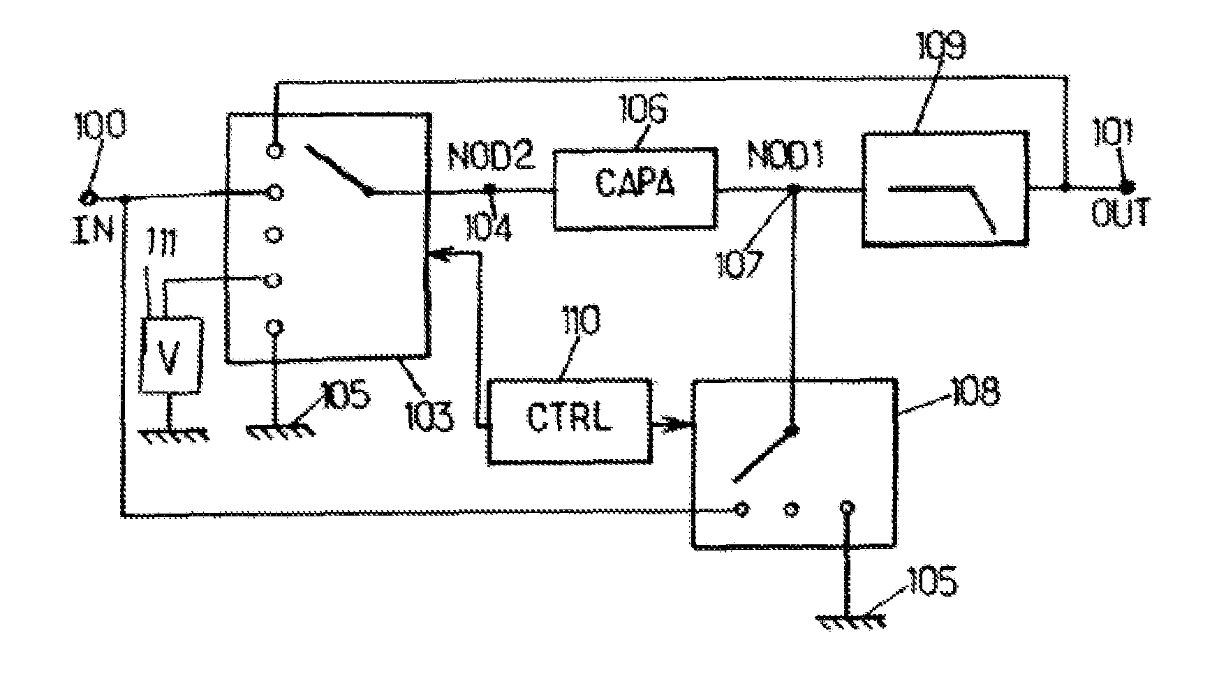
[0105]A circuit architecture according to one embodiment is now described with reference to FIG. 1.

[0106]The circuit according to this embodiment comprises an input terminal 100 for receiving a DC input voltage to be converted. For example, the terminal 100 is connected to a battery supplying a voltage to be converted.

[0107]The circuit also comprises an output terminal 101 providing a DC output voltage substantially proportional to the input voltage.

[0108]The input terminal is connected to a switching module 103. This switching module allows selectively applying different potentials to a node 104 of the circuit, as a function of the phases of operation of said circuit. For example, the switching module 103 can apply a reference potential (for example the potential of the ground 105 of the circuit), the potential of the input terminal, the potential of the output terminal, or a potential generated by a dedicated module 111. For example, said module 111 is a linear regulator which del...


PUM


Abstract

The invention proposes a direct current voltage conversion circuit which can operate as a step-up circuit, a step-down circuit, or operate as a step-up or step-down circuit depending on the modes of operation.

Description

TECHNICAL FIELD[0001]This invention relates to an electronic circuit for converting direct current (DC) voltages.[0002]The invention relates in particular to conversion circuits used in portable electronic devices such as mobile telephones or music players, for converting voltage from a battery for use in other circuits of the device, for example to modulate the output voltage from the converter for envelope detection in a radio frequency power amplifier.TECHNOLOGICAL BACKGROUND[0003]The charge pump converter architecture is used in applications where a low cost and a reduced circuit area is desired. In the adjustment of the output voltage, this architecture greatly degrades the energy efficiency, and its use is therefore limited. In addition, this type of architecture is known to generate large ripple in the output voltage, due to the fact that the current provided to the output capacitor is not direct. As a result, this type of architecture generates a lot of noise in the signals ...

Claims


Application Information

Patent Timeline
Patent Type & Authority Applications(United States)
IPC IPC(8): H02M3/155
CPCH02M3/158H02M3/07
Inventor ARNO, PATRIKPREMONT, CHRISTOPHE
Owner TELEFON AB LM ERICSSON (PUBL)
Why Eureka
Try Eureka