
Brake rod

A technology of brake levers and brake mechanisms, applied in the field of brake levers, capable of solving problems such as unauthorized

Pending Publication Date: 2019-10-29
拉季埃-菲雅克有限责任公司
View PDF0 Cites 0 Cited by
  • Summary
  • Abstract
  • Description
  • Claims
  • Application Information

AI Technical Summary

Problems solved by technology

It is hoped that breaking or disconnection of a rod in a mechanism will not cause the rod to become jammed in said mechanism, which could lead to uncommanded braking

Method used


Image

  • Brake rod
  • Brake rod
  • Brake rod

Examples


Embodiment Construction

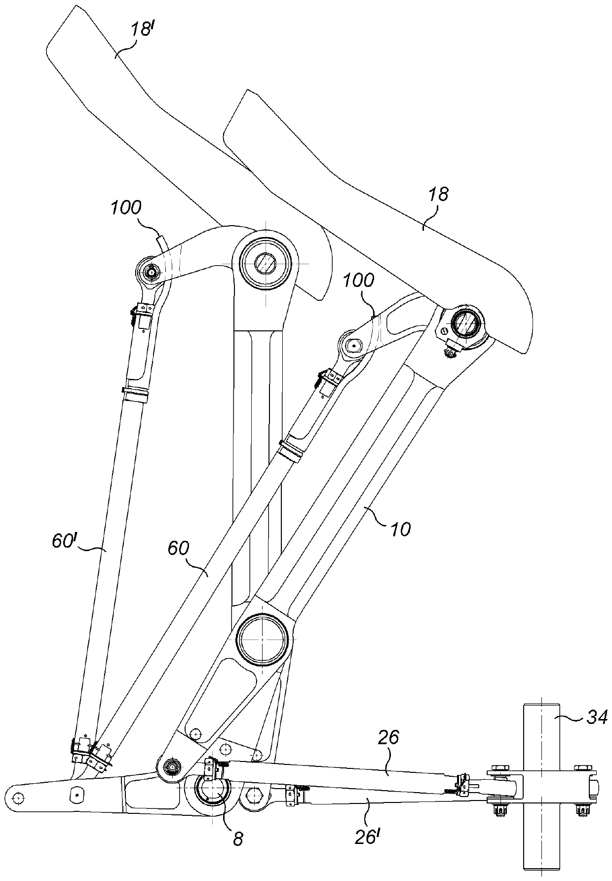
[0026] refer to Figure 1 to Figure 5 , shows a steering / braking mechanism 2 for an aircraft.

[0027] The mechanism 2 includes a base or base 4 that receives a first pivot 6 at an upper end and a second pivot 8 at a lower end ( Figure 4 ).

[0028] The first steering arm 10 is pivotably mounted about the first pivot 6 . The first steering arm 10 comprises a first clevis 12 at a first end 14 arranged on one side of the first pivot 6 . A first clevis 12 rotatably receives one end of a pedal shaft 16 in a suitable bearing. The first pedal 18 is rotatably fixedly mounted to the pedal shaft 16 by a fastener 20 .

[0029] The first steering arm 10 also includes a second clevis 22 at a second end 24 arranged on the opposite side of the first pivot 6 . A second clevis 22 is rotatably mounted to one end of a first steering rod 26 via a clevis pin 28 . The other end 30 of the first steering rod 26 is rotatably connected via a clevis connection to an arm 32 of a steering shaft 34...


PUM


Abstract

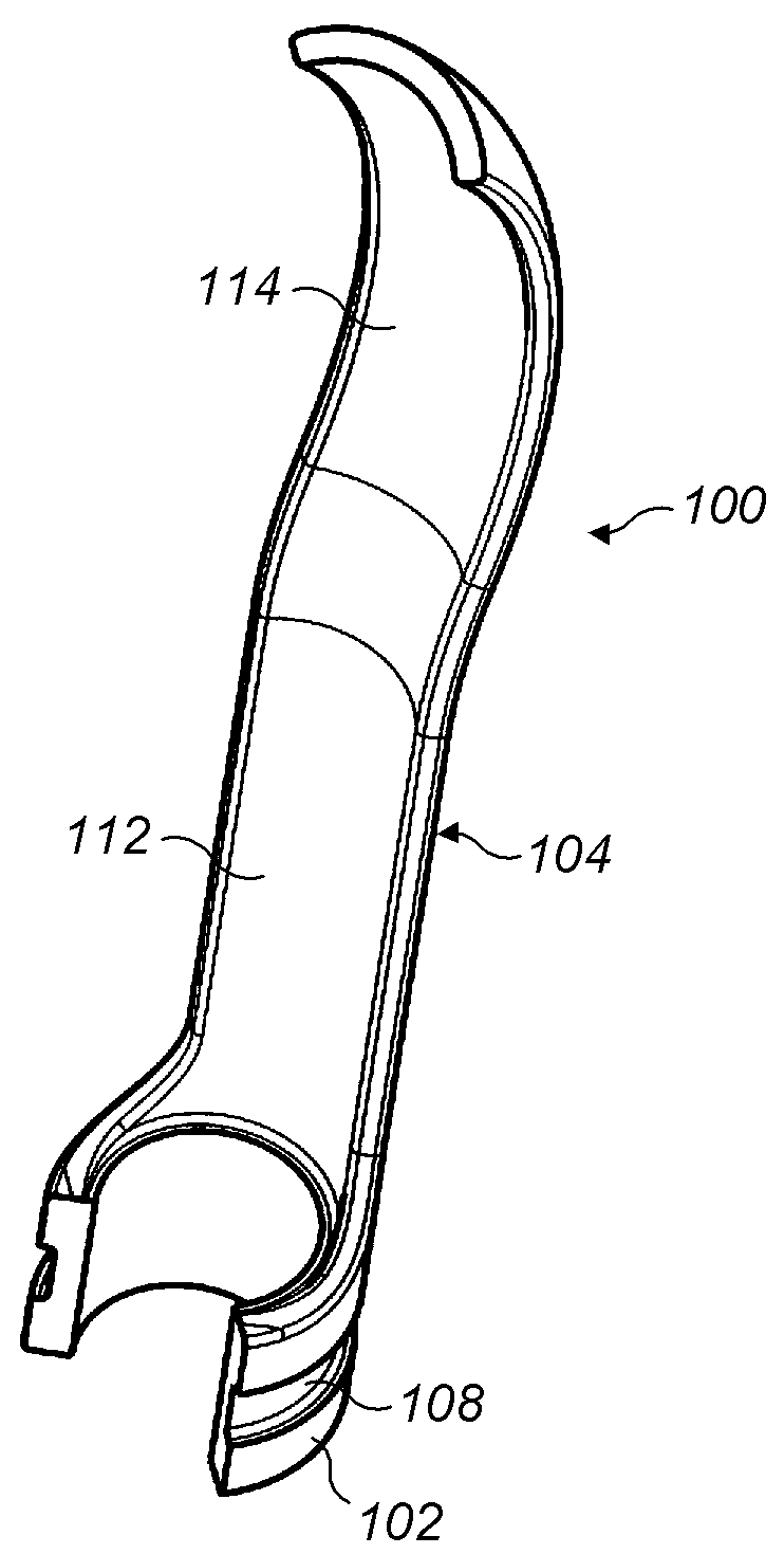
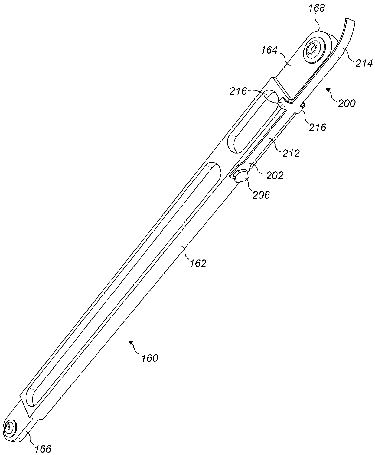
A brake rod (60) for a steering / braking mechanism (2) comprises a rod body (62) having a longitudinal axis (A), a rod end (64) at a first end of the rod body (62), the rod end (64) having a bore (68)therethrough having a bore axis (B) arranged generally perpendicular to the rod longitudinal axis (A), and a rod end shield (100) mounted to the rod (60) and extending in a longitudinal direction axially beyond the rod end (64).

Description

technical field [0001] The present disclosure relates to a brake lever, in particular to a brake lever for use in a steering / braking mechanism of an aircraft, a steering / brake incorporating said lever and a shroud for said lever mechanism. Background technique [0002] In aircraft control systems, steering and braking functions are usually provided in a single mechanism. Movement of the pedal in the first manner causes steering movement in the mechanism, and movement of the pedal in the second manner causes braking movement in the mechanism. It is hoped that breaking or disconnection of the rod in the mechanism will not cause the rod to become jammed in the mechanism, which could lead to uncommanded braking. Contents of the invention [0003] According to a first aspect, the present disclosure provides a brake lever for a steering / braking mechanism. The brake lever includes a rod body and a rod end at a first end of the rod body. The brake rod also includes a rod end s...

Claims


Application Information

Patent Timeline
Patent Type & Authority Applications(China)
IPC IPC(8): B64C25/44
CPCB64C25/44B60T7/06B60T11/18B64C13/30B64C25/34F16C7/00F16C11/045F16C11/0614F16C17/24B64C13/044F16H21/44F16H51/00F16H57/00F16H2057/0081
Inventor P-J.拉布里
Owner 拉季埃-菲雅克有限责任公司
Learn More