
Die guide pillar installation assisting equipment capable of detecting perpendicularity in real time

A mold guide post and installation assistance technology, which is applied to hand-held tools, manufacturing tools, workpiece clamping devices, etc., can solve the problems of troublesome installation process, inability to detect the verticality of guide posts in real time, etc. Effect

Active Publication Date: 2019-11-05
江苏永茂普隆汽车配件制造有限公司
View PDF7 Cites 0 Cited by
  • Summary
  • Abstract
  • Description
  • Claims
  • Application Information

AI Technical Summary

Problems solved by technology

[0005] Aiming at the deficiencies of the prior art, the present invention provides a mold guide post installation auxiliary device that can detect the verticality in real time, which has the advantages of real-time detection of the verticality of the guide post during installation, simple and convenient operation, etc. When installing a column, since the verticality of the guide column cannot be detected in real time, the installation process is very troublesome.

Method used


Image

  • Die guide pillar installation assisting equipment capable of detecting perpendicularity in real time
  • Die guide pillar installation assisting equipment capable of detecting perpendicularity in real time
  • Die guide pillar installation assisting equipment capable of detecting perpendicularity in real time

Examples


Embodiment Construction

[0026] The following will clearly and completely describe the technical solutions in the embodiments of the present invention with reference to the accompanying drawings in the embodiments of the present invention. Obviously, the described embodiments are only some, not all, embodiments of the present invention. Based on the embodiments of the present invention, all other embodiments obtained by persons of ordinary skill in the art without making creative efforts belong to the protection scope of the present invention.

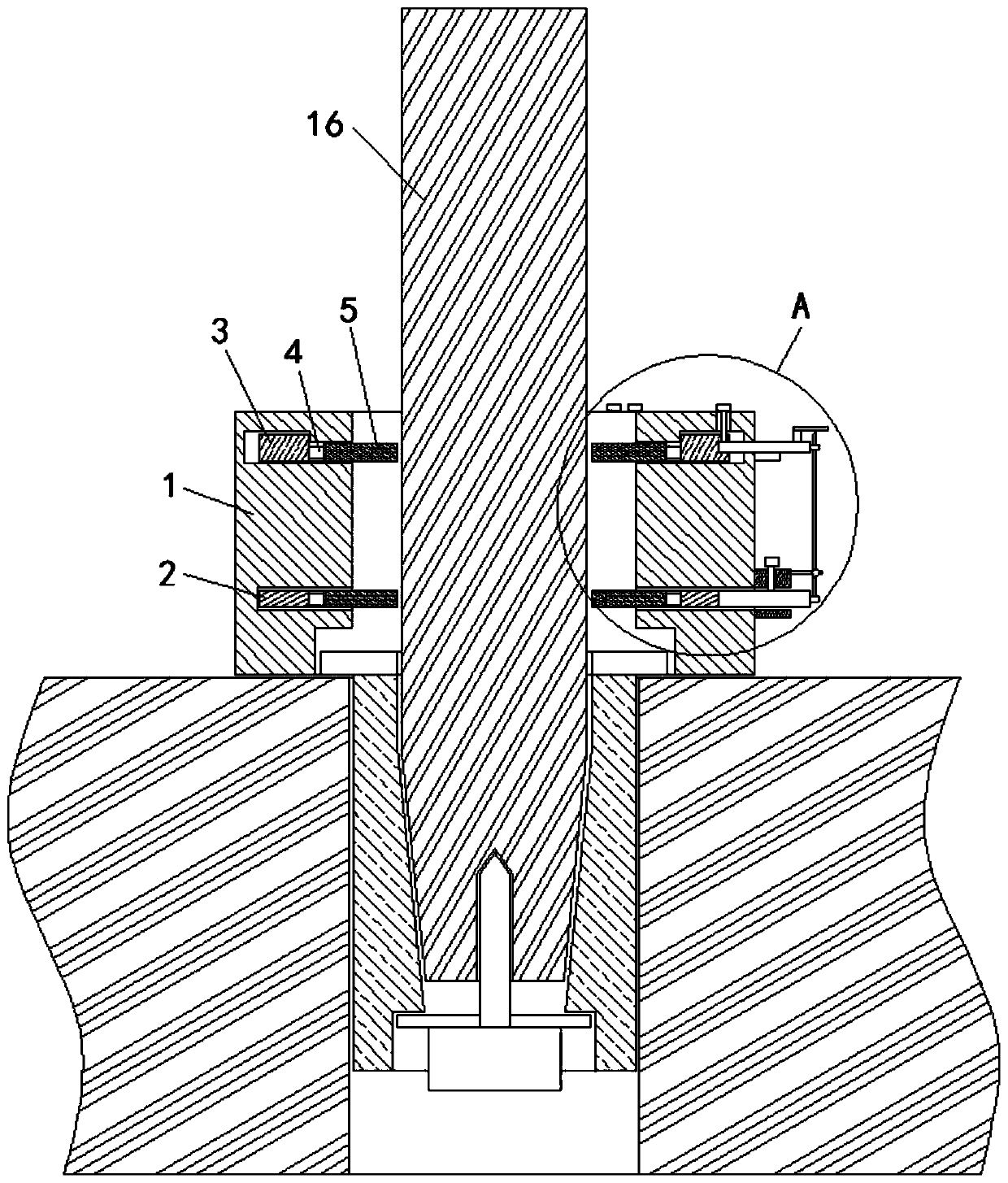
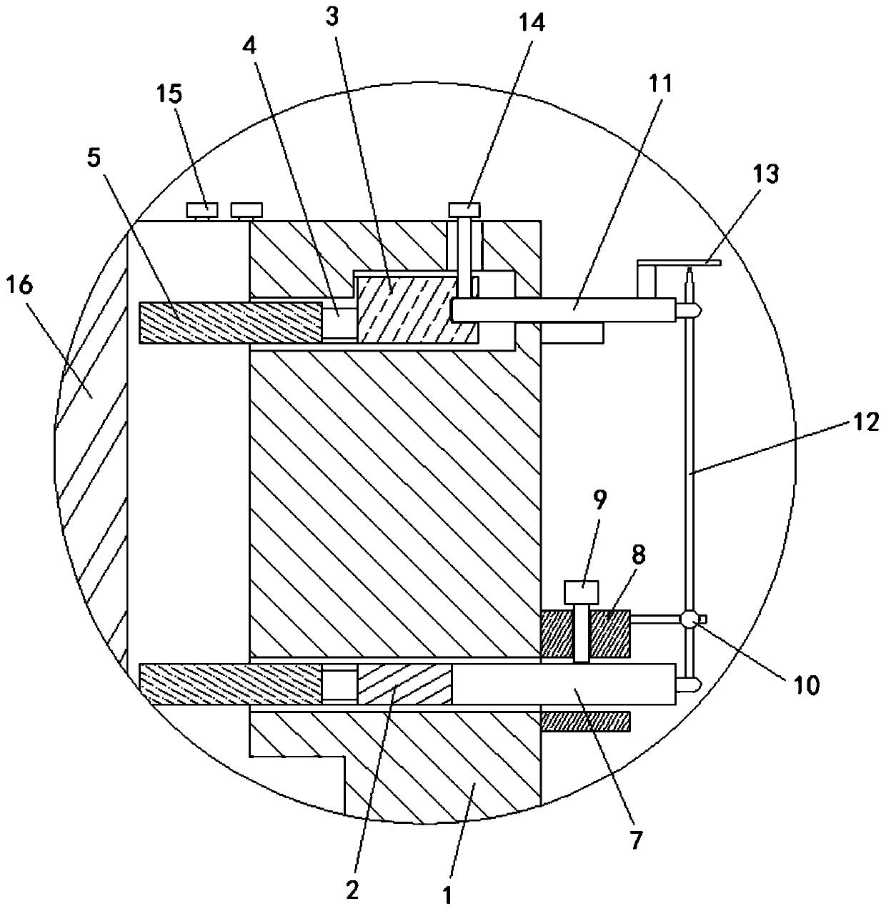
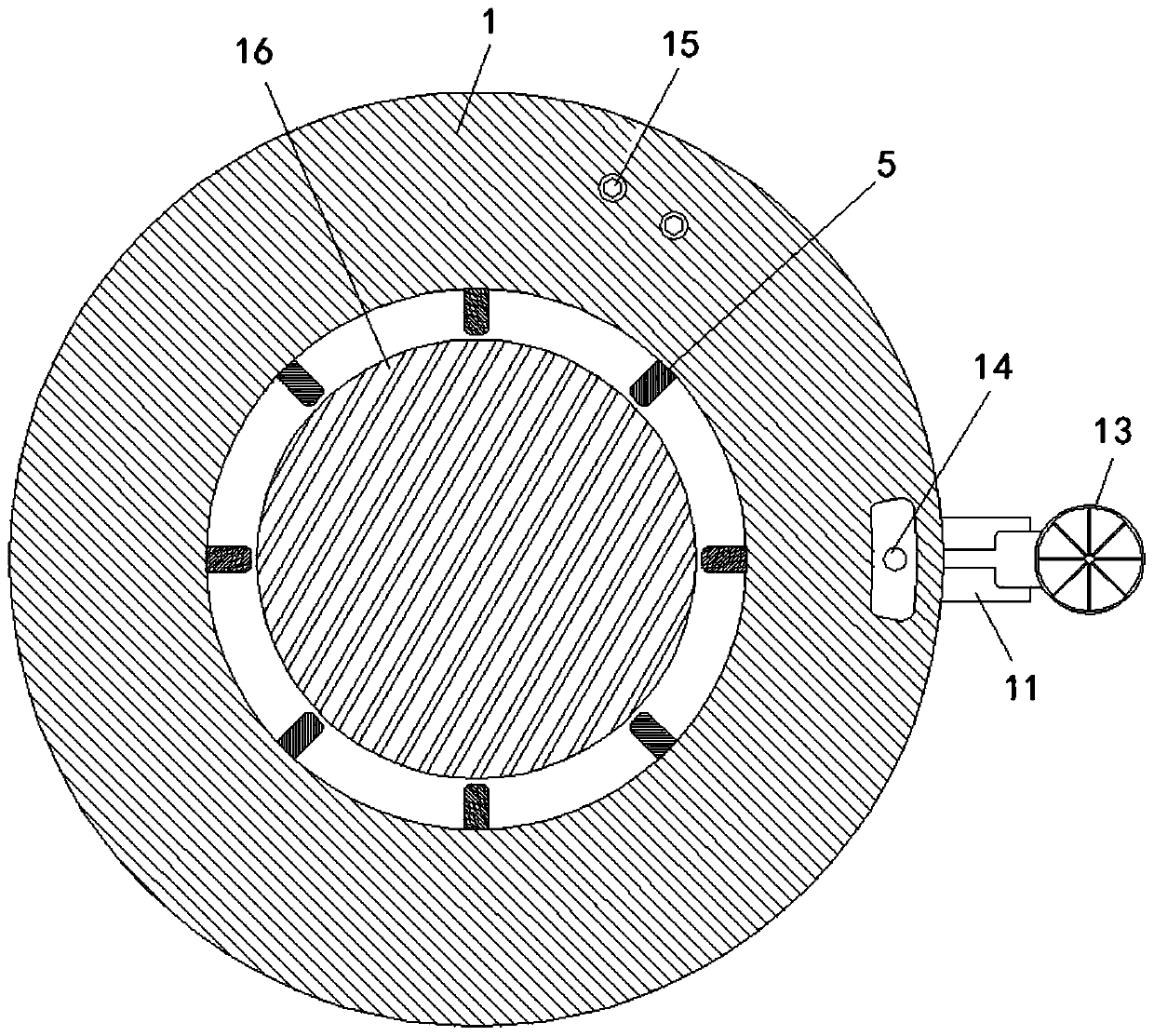
[0027] see Figure 1-7 , a mold guide column installation auxiliary equipment that can detect verticality in real time, including a support 1, a lower swivel 2 is movably connected to the lower part of the inner part of the pedestal 1, and an upper swivel 3 is movably connected to the upper part of the inner part of the pedestal 1. The inner walls of the swivel 2 and the upper swivel 3 are movably connected with clamping blocks 5 through the connecting rod 4, ...


PUM


Abstract

The invention relates to the technical field of die equipment and discloses die guide pillar installation assisting equipment capable of detecting perpendicularity in real time. The die guide pillar installation assisting equipment comprises a support, an upper rotating ring and a lower rotating ring are movably connected to the inner part of the support, and clamping blocks are movably connectedto the inner wall of the lower rotating ring and the inner wall of the upper rotating ring through connecting rods. A lower ejecting plate and an upper ejecting plate are movably connected to the right side of the support in an inserted mode, a guide base corresponding to the lower ejecting plate is fixedly connected to the right side of the support, and an indicating rod is movably connected between the right side of the upper ejecting plate and the right side of the lower ejecting plate. The lower rotating ring and the upper rotating ring are fixed to the outer side of the guide pillar through the clamping blocks, the two sets of clamping blocks are fixed through fastening bolts and locking bolts respectively, once the guide pillar deflects, the upper rotating ring also moves along withthe guide pillar, and as the indicating rod is movably installed between the right side of the upper rotating ring and the right side of the lower rotating ring, the indicating rod also deflects, andthe deflection condition of the guide pillar can be directly observed through an indication disc, so that correction can be carried out in time, and the die guide pillar installation assisting equipment is easy to operate and convenient to use.

Description

technical field [0001] The invention relates to the technical field of mold equipment, in particular to an auxiliary equipment for installing mold guide posts that can detect verticality in real time. Background technique [0002] During the working process of the stamping die, the mold guide post plays a guiding role in the movement of the upper die, which can ensure better cooperation between the upper and lower dies, thereby ensuring the dimensional accuracy of the stamping product. Therefore, the guide post plays an extremely important role. The guide post is generally installed vertically on the lower mold. In order to obtain a good guiding effect, the verticality of the guide post should be increased as much as possible during installation. If the guide post is deflected, it will not only make the gap between the upper mold and the lower mold Misalignment will directly affect the quality of the product, and will also reduce the service life of the guide post and guide ...

Claims


Application Information

Patent Timeline
Patent Type & Authority Applications(China)
IPC IPC(8): B25B11/02B25B27/02
CPCB25B11/02B25B27/02
Inventor 刘涛
Owner 江苏永茂普隆汽车配件制造有限公司
Learn More