Supercharge Your Innovation With Domain-Expert AI Agents!

Staggering type perforating machine

A technology of punching machine and case, which is applied to paper/cardboard containers, containers, bag making operations, etc., and can solve the problems of asymmetrical dislocation through-holes and inability to punch out dislocation-type through-holes in packaging bags, etc.

Pending Publication Date: 2019-11-05
张卫
View PDF0 Cites 0 Cited by
  • Summary
  • Abstract
  • Description
  • Claims
  • Application Information

AI Technical Summary

Problems solved by technology

[0003] In order to overcome the deficiency that the existing punching machine cannot make dislocation-type through holes on the front and rear bag surfaces of the packaging bag, the present invention provides a dislocation-type hole punching machine, which can simultaneously make holes on the front and rear bag surfaces of the packaging bag. The front and rear asymmetrical dislocation through holes are respectively punched on the top

Method used


Image

  • Staggering type perforating machine
  • Staggering type perforating machine
  • Staggering type perforating machine

Examples


Embodiment Construction

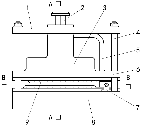
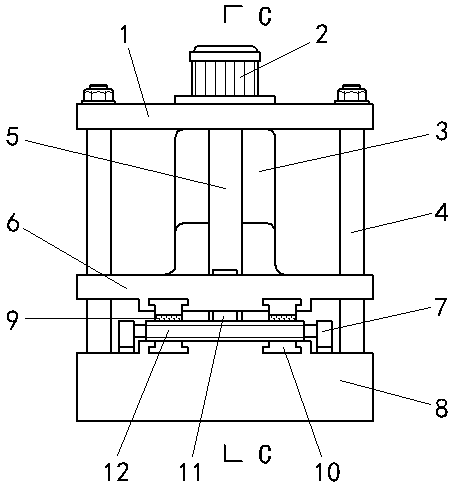
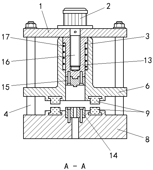
[0022] exist figure 1 , figure 2 , image 3 , Image 6 , Figure 7 , Figure 10 Among them, the top plate 1 and the bottom plate 8 are both rectangular plate structures and arranged parallel to each other up and down, and the four corners of the top plate 1 and the bottom plate 8 are connected by four columns 4 respectively. The motor 2 is connected on the top plate 1 , and the rotating shaft of the motor 2 is set as a screw shaft 16 . The die 14 is connected on the bottom plate 8, and the die 14 is a rectangular plate structure provided with several longitudinal punching holes on the transverse central axis. Front and rear slide grooves 18 parallel to the transverse central axis of the die 14 are provided on the bottom plate 8 along the front and rear sides of the die 14 , and the slide grooves 18 are dovetail groove structures. Front and rear washboards 9 are respectively arranged in the front and rear chute 18 , the upper end surface of the washboard 9 is flush with ...


PUM


Abstract

The invention discloses a staggering type perforating machine. A lifting plate is connected between a top plate and a bottom plate through stand columns. A concave mold and front and back lower washboards are arranged on the bottom plate, and the right ends of the front and back lower washboards are of rack structures and are engaged with a gear shaft. Front and back upper washboards are arrangedon the lower end face of the lifting plate. A piston and a convex mold which are connected up and down in series are arranged in a case located on the lifting plate. A screw hole in the piston is connected with a screw shaft of an electromotor located on the top plate. A transverse rod of an L-shaped drive rod is connected to the upper end of the piston. A drive rack arranged on a drive rod vertical rod corresponds to the gear shaft. A packaging bag covers the concave mold in the longitudinal direction, and when the electromotor drives the upper washboards to be in contact with the packaging bag, racks of the upper washboards and the drive rack can be engaged with the gear shaft. When the electromotor drives the upper and lower bag faces of the packaging bag to be staggered through a transmission rod, the gar shaft and the upper and lower washboards, the electromotor can drive the convex mold to perforate the packaging bag. Through holes in the upper and lower bag faces of the reset packaging bag can be staggered.

Description

technical field [0001] The invention relates to a punching machine, in particular to a dislocation punching machine capable of punching front and rear asymmetric through holes on the front and rear bag surfaces of a packaging bag. Background technique [0002] At present, when the known punching machines punch holes on the front and rear surfaces of the packaging bag at the same time, they can only punch out front and rear symmetrical through holes, but cannot punch out mutually misaligned front and rear through holes on the front and rear bag surfaces. Contents of the invention [0003] In order to overcome the deficiency that existing punching machines cannot punch out dislocation-type through holes on the front and rear surfaces of packaging bags, the present invention provides a dislocation-type hole punching machine, which can simultaneously punch holes on the front and rear surfaces of packaging bags The front and rear asymmetrical dislocation through holes are respe...

Claims


Application Information

Patent Timeline
IPC IPC(8): B31B70/14B31B160/10
CPCB31B70/142B31B2160/10
Inventor 张卫
Owner 张卫
Features
  • R&D
  • Intellectual Property
  • Life Sciences
  • Materials
  • Tech Scout
  • Unparalleled Data Quality
  • Higher Quality Content
  • 60% Fewer Hallucinations
Learn More