Chain link connecting assembly and wearable equipment

A technology for connecting components and wearable devices, applied to bracelets, watch straps, clothing, etc., can solve the problems of lack of limited wearing, complex manufacturing process of watch straps, poor user experience, etc.

Active Publication Date: 2019-11-12
NUBIA TECHNOLOGY CO LTD
View PDF9 Cites 0 Cited by
  • Summary
  • Abstract
  • Description
  • Claims
  • Application Information

AI Technical Summary

Problems solved by technology

[0003] The technical problem to be solved by the present invention lies in the complex manufacturing process of the existing terminal wearing and connecting strap, lack of limited wearing, and poor user experience; in view of this technical problem, a chain link connecting component is provided for wearable devices The wearing connection; the link connection assembly includes:

Method used


Image

  • Chain link connecting assembly and wearable equipment
  • Chain link connecting assembly and wearable equipment
  • Chain link connecting assembly and wearable equipment

Examples


no. 1 example

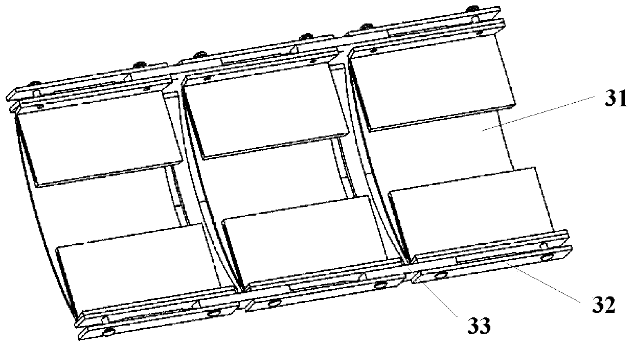
[0065] This embodiment provides a link connection assembly, which is used for wearable links of wearable devices, such as Figure 3-9 As shown, the chain link connecting assembly 30 includes at least two chain links 31, a I-shaped block 32 adjacent to the chain link 31, and a connecting piece 33 arranged between two adjacent I-shaped blocks 32, specifically , the I-shaped block 32 is connected with each chain link 31, and the I-shaped block 32 is located on the outside of the chain link 31, the I-shaped block 32 and the connecting piece 33 are connected by pins, and every two I-shaped pieces 32 are connected by a connecting piece 33 links to each other, then the I-shaped block 32 is also arranged between every two chain links 31; The connecting piece 33 and the pin connect at least two chain links 31 ; and there is an overlapping area between the connecting piece 33 and the I-shaped block 32 to ensure the stability of the chain link connecting assembly.

[0066] The I-shaped ...

no. 2 example

[0079] This embodiment provides a wearable device, such as Figure 11 , 12 As shown, it includes at least a display screen 1101, and a link connection assembly 30 located under the display screen 1101 as in the above-mentioned embodiments. The display screen 1101 is fixedly connected to the link connection assembly 30, and the wearable Wearing of the device; the display screen 1101 may include a flexible screen, and the flexible screen is set in such a way that the flexible screen is also bent correspondingly when the device is worn. like Figure 12 as shown, Figure 12 An exploded view of the wearable device provided for this embodiment.

[0080] The chain link connecting assembly 30 includes at least two chain links 31, the I-shaped block 32 connected adjacent to the chain link 31, the connecting piece 33 arranged between two adjacent I-shaped blocks 32, and the I-shaped block 32 , the connecting piece 33 and the pin connect at least two chain links 31 , wherein the pin ...


PUM


Abstract

The invention discloses a chain link connecting assembly and wearable equipment. The chain link connecting assembly comprises at least two chain links, I-shaped blocks adjacently connected with the chain links and connecting pieces arranged between every two adjacent I-shaped blocks. The at least two chain links are connected through the I-shaped blocks, the connecting pieces and pins. Each I-shaped block comprises first extension parts at the two ends and a middle piece connected with the first extension parts at the two ends. The first extension part comprises a first limiting hole. Each chain link comprises second extension parts on the two sides. The second extension parts are fixedly connected with the first extension part at one end. The connecting piece comprises T-shaped faces on the two sides and an arc-shaped face extending in the height direction of the T-shaped faces. The T-shaped surface comprises a second limiting hole. In order to solve the problems of complex watchbandmanufacturing process, lack of limiting wearing and poor user experience of wearing connection of an existing terminal due to the fact that the pins are matched with the first limiting holes and the second limiting holes to limit movable connection between the at least two chain links. The invention further discloses wearable equipment, and the limiting wearing of the wearable equipment is achieved.

Description

technical field [0001] The present invention relates to the technical field of terminals, and more specifically, to a link connection component and a wearable device. Background technique [0002] At present, with the development of smart wearable devices, especially under the trend of continuous development and breakthrough of flexible screen technology, people are also constantly pursuing the wearing connection of smart watches and smart bracelets; and in the existing technology, for most Most of the watch straps of smart wearable devices are processed by powder metallurgy or computer digital control precision machining CNC. The manufacturing process is complicated and the production cost is high. The circular holes are connected. This requires the axis of the pin shaft to be on the screen body, otherwise there is a risk of straining the screen body, and the experience pursued by the existing terminals is often "wearable", that is, it can be worn, and there is a lack of s...

Claims


Application Information

Patent Timeline
Patent Type & Authority Applications(China)
IPC IPC(8): A44C5/02A44C5/00
CPCA44C5/0007A44C5/02
Inventor 里强王德全
Owner NUBIA TECHNOLOGY CO LTD
Why Eureka
Try Eureka