
Retractor core shaft assembly and safety belt retractor

A retractor and mandrel technology, which is applied in the field of safety belts, can solve problems such as the unsatisfactory force-limiting capacity of the retractor mandrel assembly, and achieve the effects of improving force-limiting capacity, increasing frictional resistance, and extending force-limiting travel

Pending Publication Date: 2019-12-13
SHENYANG JINBEI JINHENG AUTOMOBILE SAFETY SYST CO LTD
View PDF0 Cites 0 Cited by
  • Summary
  • Abstract
  • Description
  • Claims
  • Application Information

AI Technical Summary

Problems solved by technology

[0003] However, the force-limiting capability of the retractor mandrel assembly in the related art is not ideal yet.

Method used


Image

  • Retractor core shaft assembly and safety belt retractor
  • Retractor core shaft assembly and safety belt retractor
  • Retractor core shaft assembly and safety belt retractor

Examples


Embodiment 1

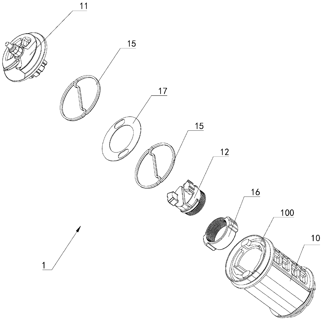
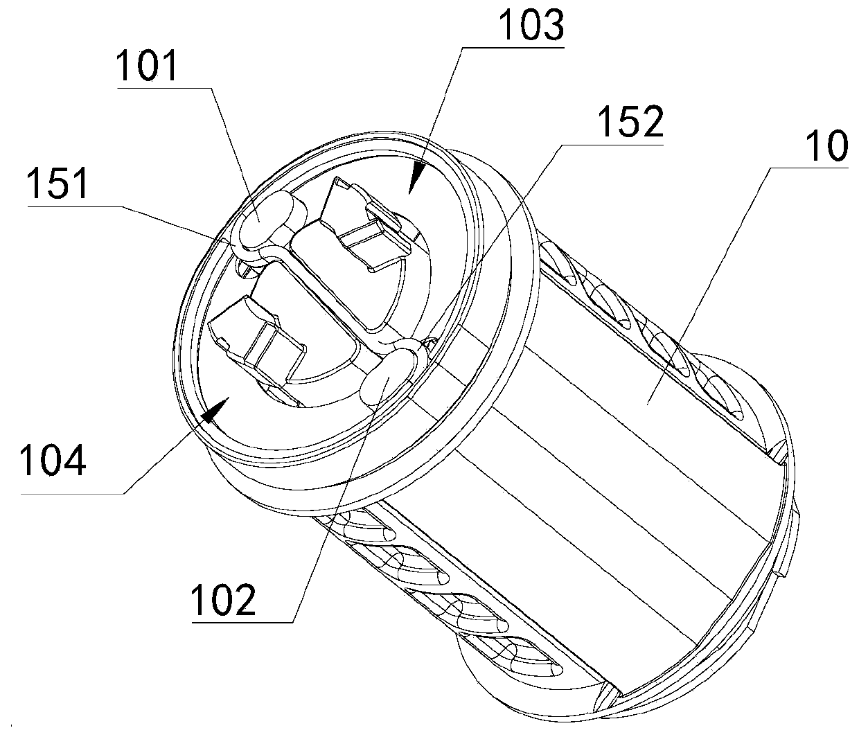
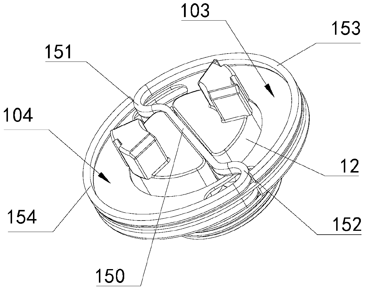
[0044] see Figure 1 to Figure 8 As shown, this embodiment provides a retractor mandrel assembly; figure 1 An exploded view of the retractor mandrel assembly provided for this embodiment, in which the structure of the retractor mandrel assembly is simply shown; figure 2 A schematic structural view of the first embodiment of the retractor mandrel assembly provided in this embodiment; image 3 for figure 2 A partial schematic view of the retractor mandrel assembly in , clearly showing the figure 2 The relative positional relationship between the multiple force limiting rings and the torque head; Figure 4 A schematic structural view of the second embodiment of the retractor mandrel assembly provided in this embodiment; Figure 5 for Figure 4 A partial schematic view of the retractor mandrel assembly in , clearly showing the Figure 4 The relative positional relationship between the multiple force limiting rings and the torque head; Image 6 A schematic structural view...

Embodiment approach

[0066] In the alternative scheme of this embodiment, see figure 2 with image 3 As shown, the second end surface 120 is provided with an installation groove 121 , and the fixing portions 150 of the plurality of force limiting rings 15 are all fitted in the installation groove 121 . This is the first implementation of the retractor mandrel assembly 1. Specifically, when the first push block 101 abuts against the first push portion 151 and the second push block 102 abuts against the second push portion 152, the Under the combined action of the installation groove 121 and the first push block 101, the two ends of the first push portion 151 are out of sync, so that as the mandrel 10 starts to rotate, the first push block 101 will directly push the first extension portion 153 Winding on the outer circumference of the torque head 12, similarly, under the joint action of the installation groove 121 and the second pushing part 152, the two ends of the second pushing part 152 are asy...

Embodiment 2

[0092]Embodiment 2 provides a seat belt retractor, which includes the retractor spindle assembly in Embodiment 1, and the technical features of the retractor spindle assembly disclosed in Embodiment 1 are also applicable to this embodiment , Embodiment 1 The technical features of the disclosed retractor mandrel assembly will not be described repeatedly.

[0093] see Figure 9 combine Figure 1 to Figure 8 As shown, the seat belt retractor 2 provided in this embodiment includes the retractor spindle assembly 1 provided in the first embodiment.


PUM


Abstract

The invention relates to the technical field of safety belts, in particular to a retractor core shaft assembly and a safety belt retractor. The retractor core shaft assembly comprises a core shaft, ashaft head, a torsion rod, a torsion head and a plurality of force-limiting rings, wherein one end of the torsion rod is fixedly connected with one end of the core shaft; the other end of the torsionrod is fixedly connected with the shaft head through the torsion head; the end face at the other end of the core shaft is a first end face; a pushing component is arranged on the first end face; at least part of the torsion head protrudes out of the first end face; the end surface, protruding out of the first end surface, by the torsion head, is the second end surface; the force-limiting rings areoverlapped in the axial direction of the torsion head and are positioned between the shaft head and the core shaft; part of the force-limiting rings are connected with the second end face, and the other part of the force-limiting rings is wound on the pushing component; and the pushing component can rotate along with the core shaft and pushes the other part of the force-limiting rings to be woundon the torsion head. The safety belt retractor comprises the retractor core shaft assembly. The retractor core shaft assembly and the safety belt retractor greatly improve the force limiting capacityto the core shaft.

Description

technical field [0001] The invention relates to the technical field of safety belts, in particular to a retractor mandrel assembly and a safety belt retractor. Background technique [0002] In the core shaft assembly of the retractor in the related art, after the seat belt is locked, the shaft head and the torque head are fixed and cannot rotate, but the mandrel will continue to rotate as the seat belt is pulled out. Usually, the torsion rod and a force limiting ring are connected between the torsion head and the mandrel to prevent the seat belt from driving the mandrel to continue to rotate, so as to achieve the effect of force limitation. [0003] However, the force-limiting capability of the retractor mandrel assembly in the related art is still not ideal. Therefore, it is urgent to propose a retractor mandrel assembly with better force-limiting ability to the mandrel. Contents of the invention [0004] The purpose of the present invention is to provide a retractor ma...

Claims


Application Information

Patent Timeline
Patent Type & Authority Applications(China)
IPC IPC(8): B60R22/46
CPCB60R22/46
Inventor 胡晏殊李明阳韩非胡大为吴伟魏旺刘彦广
Owner SHENYANG JINBEI JINHENG AUTOMOBILE SAFETY SYST CO LTD
Learn More