A method for calibrating key parameters of electric vehicle asynchronous motor

A technology for asynchronous motors and electric vehicles, applied in electric vehicles, motor generator control, electronic commutation motor control, etc., can solve the problems that the motor cannot be strictly guaranteed, and the asynchronous motor cannot maintain the optimal current and ratio state, etc., to achieve The effect of fine state adjustments

Active Publication Date: 2021-03-02
ANHUI UNIVERSITY
View PDF7 Cites 0 Cited by
  • Summary
  • Abstract
  • Description
  • Claims
  • Application Information

AI Technical Summary

Problems solved by technology

In fact, only the calibration of the physical model parameters of the motor can only make the motor output the maximum torque at the current current, but this does not mean that the motor can output the torque command with the minimum current. For example, the patent "A method based on improved In "Asynchronous Motor Parameter Identification Method Based on Particle Swarm Optimization Algorithm (CN106953577B)", only the time constant of the rotor of the asynchronous motor is calibrated, and the d and q axis currents are not adjusted according to different speed and torque commands. Obviously, the asynchronous The motor is kept at the optimal current ratio state; as another example, in the patent "Asynchronous motor key information tracking method based on improved particle swarm algorithm (CN104362927A)", only the rotor time constant and excitation inductance are adjusted. Adjusting the d and q axis currents with the torque command cannot keep the asynchronous motor in the optimal current ratio state
Therefore, the traditional calibration method of electric vehicle asynchronous motor parameters can only make the motor run at a higher torque and higher efficiency state, but it cannot strictly guarantee that the motor can run at the optimal torque under any torque command. state of current ratio

Method used


Image

  • A method for calibrating key parameters of electric vehicle asynchronous motor
  • A method for calibrating key parameters of electric vehicle asynchronous motor
  • A method for calibrating key parameters of electric vehicle asynchronous motor

Examples


Embodiment Construction

[0038] The present invention will be further described below in conjunction with the accompanying drawings.

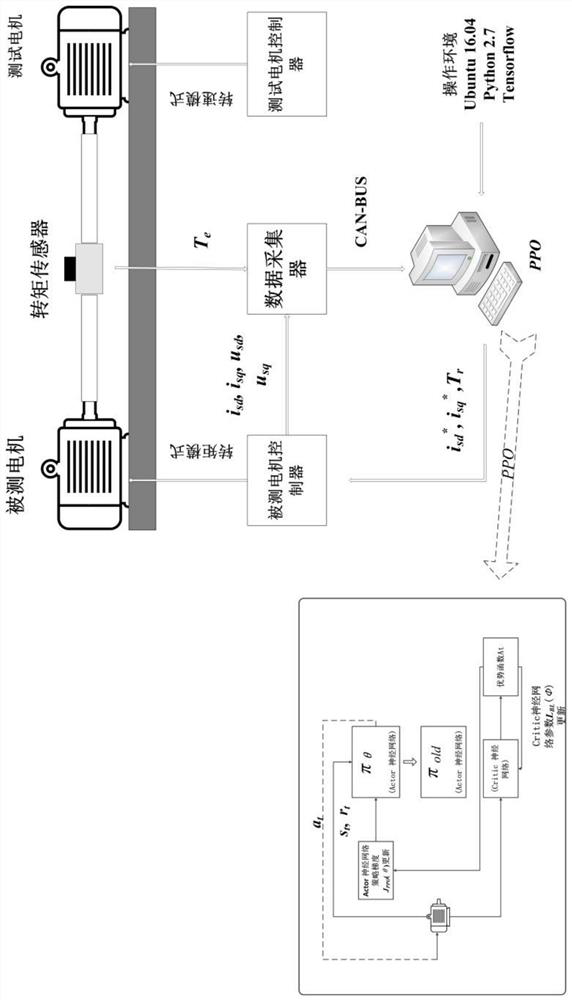
[0039] Such as figure 1 Shown, the instrument equipment that the system of the present invention needs has:

[0040] 1. One motor pair pulls the bench, and the motor of the dynamometer and the motor under test are coaxially installed on the bench. The motor under test is the electric vehicle asynchronous motor that needs to calibrate key parameter values. The function of the motor of the dynamometer is to The motor under test provides the load and supports the speed of the motor under test. The motor of the dynamometer can be an asynchronous motor or a synchronous motor;

[0041] 2. There are two motor controllers, which are the motor controller under test for controlling the motor under test on the drag stand and the motor controller for the dynamometer controlling the motor of the dynamometer;

[0042] 3. One speed-torque sensor, installed between the motor of the ...


PUM


Abstract

The invention discloses a method for calibrating key parameters of an asynchronous motor of an electric vehicle, which is aimed at different rotation speeds n and different torque commands T at the current rotation speed on the motor pairing platform e * , the Proximal Policy Optimization (PPO) algorithm is used to calibrate the d-axis given current value, q-axis given current value and rotor time constant value of the electric vehicle asynchronous motor, and the calibrated results are expressed as The table form is stored in the motor controller, so that the electric vehicle asynchronous motor can query and use this parameter during actual operation. The method of the present invention not only calibrates the rotor time constant of the electric vehicle asynchronous motor, but also calibrates the d-axis given current of the motor and q-axis given current, at the same time, the calibrated parameters can make the motor at any speed n and torque command T e * Both have the characteristic of maximum torque current ratio.

Description

technical field [0001] The invention relates to the technical field of motor control, in particular to a method for acquiring key parameters of an asynchronous motor based on an electric vehicle. Background technique [0002] In the field of modern electric vehicle technology, power performance and cruising range are the key issues for the development of electric vehicles, and electric vehicle motors are the heart of electric vehicles. The performance of the motor directly affects the overall performance of electric vehicles. Generally speaking, during the operation of electric vehicles, it is hoped that the motor can accurately respond to the torque command issued by the vehicle controller, and the motor can always maintain the optimal torque-current ratio (that is, use the minimum current output Maximum torque), thereby improving the efficiency of the motor and extending the cruising range of the vehicle. [0003] In the field of motor control of electric vehicles, in ord...

Claims


Application Information

Patent Timeline
Patent Type & Authority Patents(China)
IPC IPC(8): H02P21/14H02P21/16B60L15/20
CPCB60L15/20H02P21/14H02P21/16Y02T10/64Y02T10/72
Inventor 漆星郑常宝
Owner ANHUI UNIVERSITY
Why Eureka
Try Eureka