Whirling well outer wall template construction method

A construction method and swirling well technology, which can be used in excavation, artificial islands, water conservancy projects, etc., can solve the problems of consuming labor, formwork, scaffolding and time, increasing the amount of earthwork excavation, and many construction procedures, so as to reduce earthwork excavation The effect of reducing the amount of excavation, shortening the construction period, and avoiding earthwork backfilling

Active Publication Date: 2019-12-31
CHINA MCC5 GROUP CORP
View PDF4 Cites 1 Cited by
  • Summary
  • Abstract
  • Description
  • Claims
  • Application Information

AI Technical Summary

Problems solved by technology

Using this method increases the amount of earthwork excavation, and the thickness of the shaft wall is usually about 2m. It is not possible to use conventional thick wall protection as the outer formwork, which consumes a lot of labor, formwork, scaffolding and time, and has many construction procedures, which is uneconomical.

Method used


Image

  • Whirling well outer wall template construction method
  • Whirling well outer wall template construction method

Examples


Embodiment 1

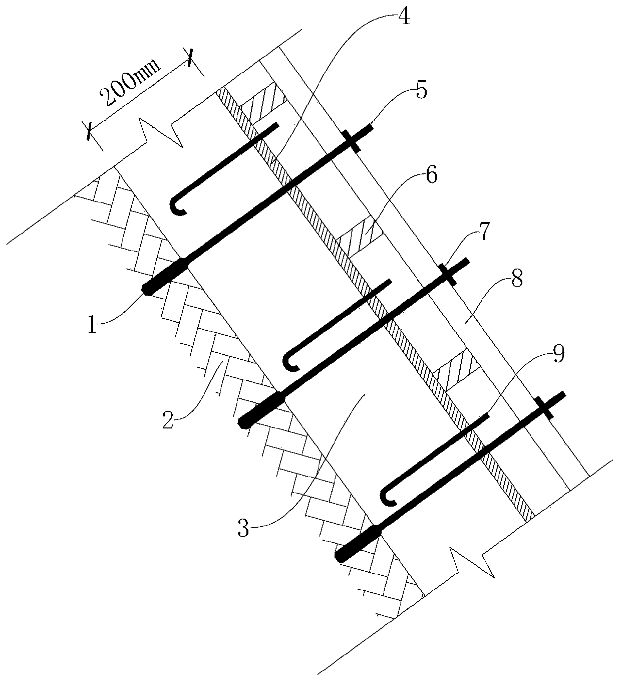
[0035] Such as figure 1 and figure 2 Shown, a kind of swirling well outer wall formwork construction method comprises:

[0036] Earthwork excavation steps: during the earthwork excavation construction of the swirl well, dig xmm more outward along the well wall 10;

[0037] Drilling and installation steps: use a drill to drill holes on the rock base at the 3 positions of the retaining wall, the drilling distance is ymm*ymm, and the drilling depth is ≥100mm. After cleaning the hole, install the expansion bolt 1 in the hole;

[0038] Reinforcement installation steps: bind reinforcement mesh on the base of retaining wall 3;

[0039] Installation steps of the first formwork: the first formwork (retaining wall 3 formwork) is reinforced with the first pair of water-stop screw rods 5 (double bolts). 1 The welding is firm, and the expansion bolt 1 is passed through the first formwork (wooden formwork), and the installation and reinforcement of the first formwork are carried out;

...

Embodiment 2

[0048] In this embodiment, specific structural details are optimized, making the entire construction method easier to implement.

[0049] Such as figure 1 As shown, the construction structure of the retaining wall 3 at the inclined well wall 10 of the swirling well includes the first formwork, the first pair of water-stop screw rods 5, the first pad, the first reinforcement rod and the expansion bolts fixed in the bedrock 2 1;

[0050] The first pair of water-stop screws 5 are welded with expansion bolts 1 and pass through the first template; the first pad is arranged outside the first template, and the first reinforcement rod is installed on the first pad; the first pair of water-stop screws 5 The ends are fixed by fasteners; the embedded parts are fixed on the first template.

[0051] The retaining wall 3 at the inclined well wall 10 of the swirling well is designed as a 200mm thick reinforced concrete structure, that is, the distance between the first template and the fou...

Embodiment 3

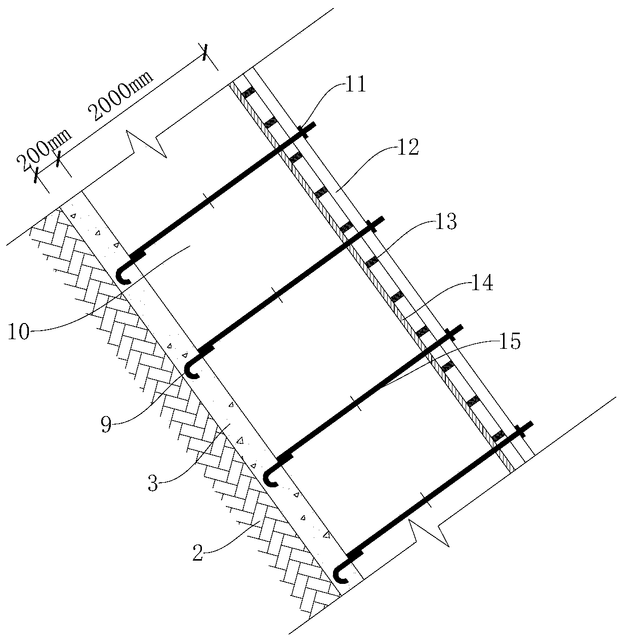
[0055] Such as figure 2 As shown, the present invention optimizes the formwork construction structure of the well wall 10, and the formwork construction structure of the well wall 10 includes a second formwork, a second pair of pulling water-stop screws 15, a second cushion block, and a second reinforcement rod;

[0056] The second pair of pull water-stop screw rods 15 are welded with the embedded parts embedded in the retaining wall 3 and pass through the second template; the second template is provided with a second cushion block, and the second reinforcement rod is installed on the second cushion block; the second The ends of the water stop screw 15 are fastened by a fixing piece.

[0057] After the reinforced concrete retaining wall 3 is poured, remove the retaining wall 3 wooden formwork (the second formwork) and carry out the swirling well wall 10 steel bar binding, and simultaneously pull the well wall 10 pairs of water-stop screws (the second pair of water-stop screws...


PUM

PropertyMeasurementUnit
Exposed lengthaaaaaaaaaa
Thicknessaaaaaaaaaa

Abstract

The invention discloses a whirling well outer wall template construction method. The whirling well outer wall template construction method includes an earth excavation step, a drilling and installingstep, a reinforcing steel bar installing step, a first template installing step, an embedded part arrangement step, a concrete pouring step, a second opposite pulling water stop screw welding step anda second template fixing and pouring step, wherein the drilling and installing step includes: using a drill bit to drill holes in a rock base layer on a retaining wall, setting the drilling intervalas y mm*y mm, setting the drilling depth to be larger than or equal to 100 mm, and installing expansion bolts in the holes after the holes are cleaned up, and the embedded part arrangement step includes: embedding embedded parts according to the following mode of setting the transverse interval as z mm and setting the lengthways interval as z mm in construction of reinforced concrete retaining wall bars or installation of a first template. A 200 mm thick reinforced concrete structure designed through the whirling well outer wall template construction method not only can be used as a whirling well foundation pit retaining wall, but also can be used as a template on the outer side of the tapered well wall of a whirling well, thereby achieving double benefit, and the retaining wall template is simple, efficient and quick to construct, and furthermore the whirling well outer wall template construction method improves construction quality of the well wall of the whirling wall, and shortensthe construction period of the whirling well.

Description

technical field [0001] The invention belongs to the field of industrial building construction, and in particular relates to a construction method of a formwork for the outer wall of a swirl well. Background technique [0002] In the construction of reinforced concrete swirling well-shaped shaft wall foundation pit in industrial buildings, the treatment of foundation pit side slope earthwork is usually carried out by spraying method for retaining wall construction. After the earthwork grading and excavation is completed, the steel mesh is bound and sprayed, and then the conical well wall formwork frame is set up, the formwork is installed and reinforced, and the formwork is removed after the conical well wall concrete pouring of the swirl well is completed. frame and well wall wooden formwork, and finally earth backfilling. Using this method increases the amount of earthwork excavation, and the thickness of the shaft wall is usually about 2m. It is not possible to use conven...

Claims


Application Information

Patent Timeline
IPC IPC(8): E02D29/12E02D17/08
CPCE02D17/08E02D29/12
Inventor 陈昌俊
Owner CHINA MCC5 GROUP CORP
Why Eureka
Try Eureka