Non-contact and non-destructive optical fiber patch cord and manufacturing method thereof

A fiber optic jumper, non-contact technology, applied in the field of communication, can solve the problems of inaccurate test results, four-way, poor interchangeability, female adapter failure, etc., to achieve non-contact non-destructive docking, avoid The effect of butt damage and avoidance of cleaning damage

Pending Publication Date: 2019-12-31
四川天勤通科技有限公司
View PDF0 Cites 6 Cited by
  • Summary
  • Abstract
  • Description
  • Claims
  • Application Information

AI Technical Summary

Problems solved by technology

[0006] In the dismantling and repairing technology mentioned above, when the jumper is connected to the jumper, the damage of the ceramic end face can be repaired by secondary grinding because the ceramic end face is exposed. Although it can be repaired, the cost is high, and the 3D index of the product after repair is The repeatability of plugging and unplugging, four-way, interchangeability and other quality are not good, and the number of repairs is limited, especially for the female adapter, which is basically invalid. After the end face of the female adapter is damaged, it is basically scrapped.
[0007] In the above-mentioned dismantling and repairing technology, the non-contact end-face protection of the optical fiber is realized by the isolation of the attenuation sheet. Due to the additional gasket, the ceramic ferrules outside the two optical fiber jumpers cannot be tightly connected. In addition to the increase in insertion loss, there are also serious problems. Reliability and stability, resulting in inaccurate test results and even failure of fiber link connections

Method used


Image

  • Non-contact and non-destructive optical fiber patch cord and manufacturing method thereof
  • Non-contact and non-destructive optical fiber patch cord and manufacturing method thereof
  • Non-contact and non-destructive optical fiber patch cord and manufacturing method thereof

Examples


Embodiment Construction

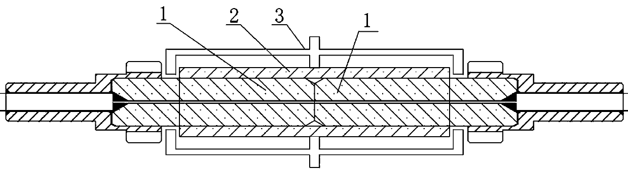
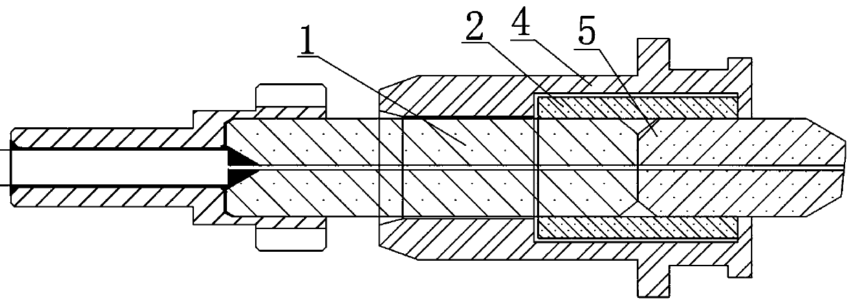
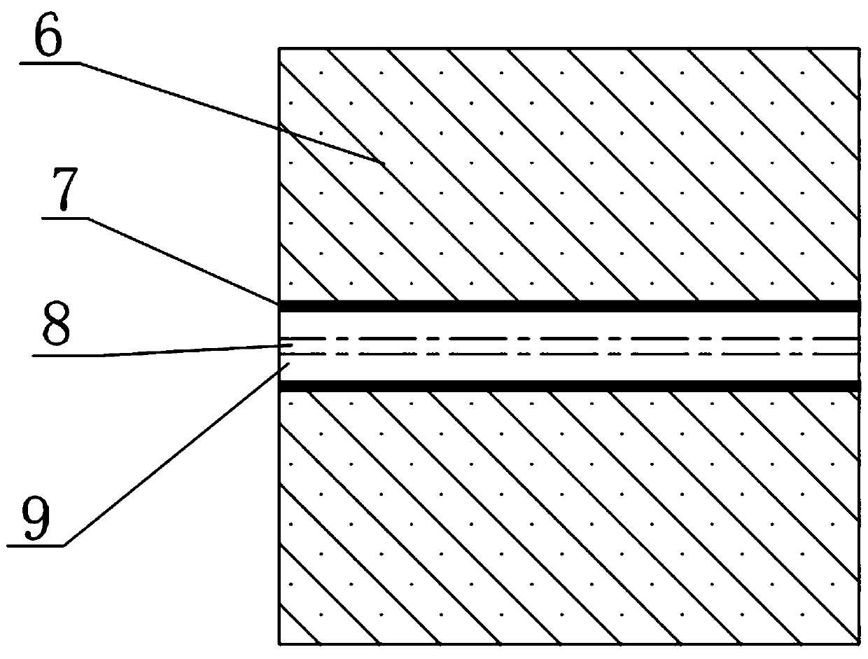
[0034] The present invention will be further described below in conjunction with the accompanying drawings, but the protection scope of the present invention is not limited to the following description.

[0035] In the description of the present invention, unless otherwise stated, the meaning of "plurality" is two or more; the terms "upper", "lower", "left", "right", "inner", "outer" , "front end", "rear end", "head", "tail", etc. indicate the orientation or positional relationship based on the orientation or positional relationship shown in the drawings, and are only for the convenience of describing the present invention and simplifying the description, rather than Nothing indicating or implying that a referenced device or element must have a particular orientation, be constructed, and operate in a particular orientation should therefore not be construed as limiting the invention. In addition, the terms "first", "second", "third", etc. are used for descriptive purposes only ...


PUM


Abstract

The invention relates to the technical field of communication, and specifically discloses a non-contact and non-destructive optical fiber patch cord and a manufacturing method thereof. The non-contactand non-destructive optical fiber patch cord comprises a ceramic ferrule, an adapter metal shell, a ceramic sleeve, an adapter segment ferrule and an optical fiber, wherein an optical fiber is buriedin the ceramic ferrule and the adapter segment ferrule in advance, one end of the ceramic ferrule is in butt joint with one end of the adapter segment ferrule, the ceramic sleeve is arranged at the outside of the butt joint site of the ceramic ferrule and the adapter segment ferrule, the ceramic sleeve is arranged in the adapter metal shell, the non-contact and non-destructive optical fiber patchcord is characterized in that an annular groove is formed in an end face of the ceramic ferrule along the periphery of the optical fiber. The non-contact and non-destructive optical fiber patch cordprovided by the invention has the advantages of realizing non-contact alignment of a jumper and a jumper, and of the jumper and an end face of the optical fiber in an adapter, and avoiding butt jointdamage to the end face of the optical fiber.

Description

technical field [0001] The invention relates to the technical field of communication, in particular to a non-contact lossless optical fiber jumper and a manufacturing method thereof. Background technique [0002] The existing optical fiber communication technology has been widely used in various fields. With the increase of transmission rate and distance, the requirements for the quality of optical fiber communication and the quality of optical fiber end face are getting higher and higher. Optical fiber docking is very different from the original cable docking, as long as the cable is in good contact, but fiber optic end-to-face docking needs to be strictly controlled in terms of up and down, left and right, front and back, and inclination angles to achieve good insertion loss requirements. The part of the optical fiber that is actually used for light transmission is small in size, basically on the order of microns, and is inconvenient for docking operations. In actual use, ...

Claims


Application Information

Patent Timeline
Patent Type & Authority Applications(China)
IPC IPC(8): G02B6/38
CPCG02B6/3825G02B6/3847G02B6/3869
Inventor 王强刘萍罗霄王晓容
Owner 四川天勤通科技有限公司
Why Eureka
Try Eureka