
Rendering method of display panel, display panel and display device

A display panel and display area technology, applied in the direction of identification devices, static indicators, instruments, etc., can solve the problems affecting the display effect and achieve the effect of improving the display effect

Active Publication Date: 2020-01-03
WUHAN TIANMA MICRO ELECTRONICS CO LTD
View PDF6 Cites 11 Cited by
  • Summary
  • Abstract
  • Description
  • Claims
  • Application Information

AI Technical Summary

Problems solved by technology

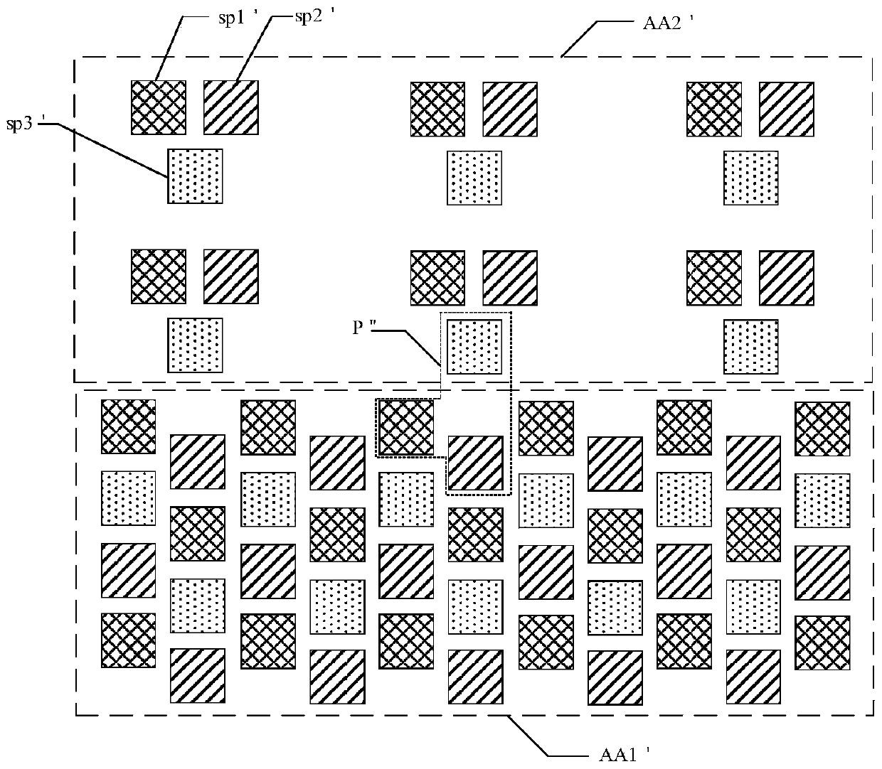
However, after increasing the brightness of a single sub-pixel in the area where the optical device is located, there will be a bright line at the junction of the area where the optical device is located and the normal display area during display, resulting in a split screen that affects the display effect

Method used


Image

  • Rendering method of display panel, display panel and display device
  • Rendering method of display panel, display panel and display device
  • Rendering method of display panel, display panel and display device

Examples


Embodiment Construction

[0028] In order to better understand the technical solutions of the present invention, the embodiments of the present invention will be described in detail below in conjunction with the accompanying drawings.

[0029] It should be clear that the described embodiments are only some of the embodiments of the present invention, not all of them. Based on the embodiments of the present invention, all other embodiments obtained by persons of ordinary skill in the art without creative efforts fall within the protection scope of the present invention.

[0030] Terms used in the embodiments of the present invention are only for the purpose of describing specific embodiments, and are not intended to limit the present invention. As used in the embodiments of the present invention and the appended claims, the singular forms "a", "said" and "the" are also intended to include the plural forms unless the context clearly indicates otherwise.

[0031] It should be understood that the term "an...


PUM


Abstract

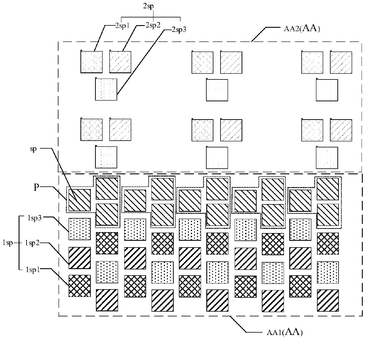
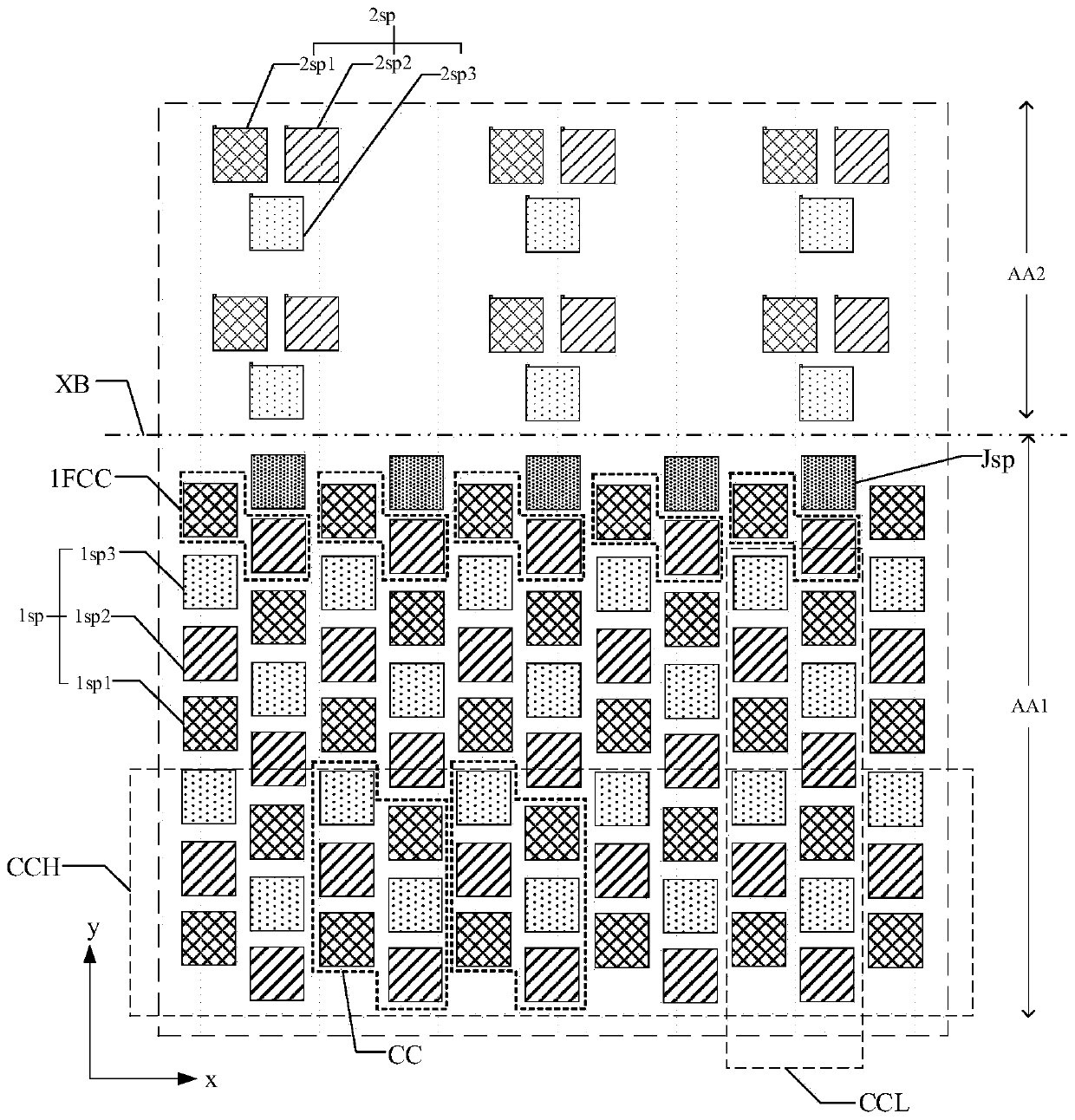
The invention provides a rendering method of a display panel, the display panel and a display device. The display panel includes: a display area including a first display area and a second display area; AND sub-pixels which comprise first sub-pixels and second sub-pixels, wherein the first sub-pixels are located in the first display area, the second sub-pixels are located in the second display area, and the pixel density of the second display area is smaller than that of the first display area. The rendering method comprises the steps that the first display area performs display in a sub-pixelrendering mode, and the first sub-pixels adjacent to the second display area perform white display without the help of the second sub-pixels. According to the technical scheme provided by the embodiment of the invention, the bright line problem at the junction of the first display area and the second display area can be avoided, and the display effect is improved.

Description

【Technical field】 [0001] The present invention relates to the field of display technology, in particular to a rendering method of a display panel, a display panel and a display device. 【Background technique】 [0002] In the existing display technology, by adopting the scheme of the optical device under the screen, the optical device is arranged under the display area, thereby saving the space of the non-display area, so as to increase the screen ratio and realize a full screen. Taking the optical device as a camera as an example, when the image is displayed normally, the area where the camera is located can be displayed normally; when the camera is enabled, the light penetrates the display panel and is collected by the camera to realize the function of taking pictures or video. [0003] Due to the limited light transmission area in the display area, in order to increase the light transmittance and improve the optical performance of the optical device under the screen, the co...

Claims


Application Information

Patent Timeline
Patent Type & Authority Applications(China)
IPC IPC(8): G09G3/20G09F9/30
CPCG09G3/2074G09F9/335G09G3/3208G09G2310/0232G09G2320/02H10K59/60
Inventor 蔡敏夏志强马扬昭
Owner WUHAN TIANMA MICRO ELECTRONICS CO LTD
Learn More