Clamping anchor for fastening ironwork to hollow profile of window or door

A technology for anchors and iron products, used in threaded fasteners, friction-clamped detachable fasteners, door/window accessories, etc. Desirable, time-saving, quick and easy to install effects

Active Publication Date: 2020-02-21
埃马纽埃尔迪德里希卡米尔范帕里斯
View PDF9 Cites 2 Cited by
  • Summary
  • Abstract
  • Description
  • Claims
  • Application Information

AI Technical Summary

Problems solved by technology

Such slides cannot be clamped stably in hollow profiles

Method used


Image

  • Clamping anchor for fastening ironwork to hollow profile of window or door
  • Clamping anchor for fastening ironwork to hollow profile of window or door

Examples


Embodiment Construction

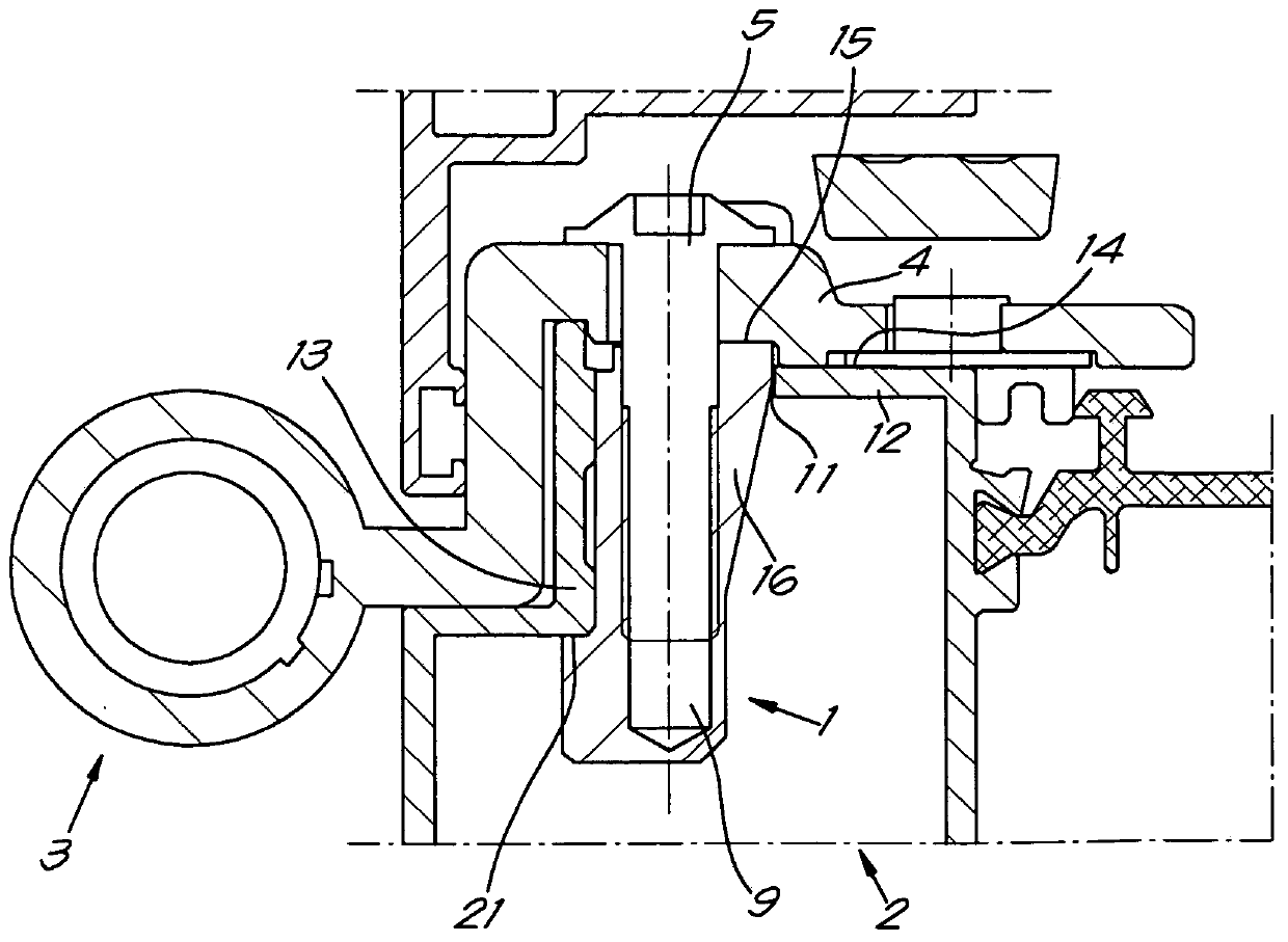
[0062] figure 2 A part of a hinge 3 is shown, a hinge leaf 4 of which is fastened to the hollow profile 2 by means of the clamping anchor 1 according to the invention.

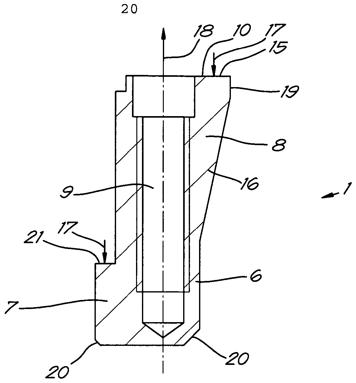
[0063] like figure 1 As shown in more detail in , the clamping anchor 1 basically consists of an L-shaped body 6 having a first leg 7 and a second leg 8 provided with an internal thread 9 along which the extending in the length direction.

[0064] The clamping anchor 1 is oblong with a long leg (second leg 8) and a short leg (first leg 7).

[0065] The bearing surface 15 is located on the free end 10 of the second leg 8 which rests on the hinge leaf 4 when the screw 5 is tightened.

[0066] As shown, this bearing surface 15 can be arranged at the head of the free end 10 of the second leg 8, but the free end 10 can also be shaped so that the bearing surface is not completely at the top, but slightly lowered so that the hinge leaf 4 It is still possible to rest on this support surface.

[0067] The free en...


PUM


Abstract

The invention relates to a clamping anchor for fastening ironwork to a hollow profile of a window or door, whereby the clamping anchor essentially consists of an L-shaped body with a first leg and a second leg, whereby the first leg is short in proportion to the second leg, the second leg of which is provided with an internal thread for securing the clamping anchor via a screw, which internal threads extends lengthways of the second leg, whereby the first leg is provided with a clamping surface for an internal wall surface of the profile, characterized in that at the free end of the second leg, a supporting surface is provided for the ironwork, whereby the clamping surface and the supporting surface are located at both sides of the thread of the second leg, whereby a stable balance of forces is created on the clamping anchor when tightening the screw. The invention also relates to a method for fastening ironwork to a hollow profile of a window or door by means of said clamping anchor.

Description

technical field [0001] The invention relates to a pinch anchor for fastening ironwork to hollow profiles of windows or doors, in particular for fastening hinges to windows or doors. Background technique [0002] In the case of windows and doors consisting of hollow profiles made of aluminum or similar material, the hinges are currently fastened to the hollow profiles by means of bolts which are inserted into the wall of the profile through openings Screwed in the tensile member, the screw hole is located opposite the opening in the wall of the profile. [0003] Such a tensile member is formed, for example, by a plate which is slid into the profile hollow space until the screw hole is opposite the drilled hole in the profile, wherein during movement the plate is pressed against the wall by means of a leaf spring or the like internal. [0004] This installation requires a certain amount of time and skill of the tradesman for that part, especially when the hinge has to be fas...

Claims


Application Information

Patent Timeline
Patent Type & Authority Applications(China)
IPC IPC(8): F16B5/02E05D11/00
CPCF16B5/02E05D11/00E05D5/023E05Y2900/148F16B2/065F16B33/002
Inventor 埃马纽埃尔·迪德里希·卡米尔·范帕里斯
Owner 埃马纽埃尔迪德里希卡米尔范帕里斯
Why Eureka
Try Eureka