Paper pushing mechanism

A technology of push rod and driving motor, applied in stack receiving device, thin material handling, transportation and packaging, etc., can solve the problems of paper bending, damage, increase the workload of staff, etc. The effect of paper efficiency

Active Publication Date: 2020-02-25
北京太章机电设备有限公司
View PDF6 Cites 2 Cited by
  • Summary
  • Abstract
  • Description
  • Claims
  • Application Information

AI Technical Summary

Problems solved by technology

Due to the limited size of the cavity, the method of manually picking up paper is cumbersome, which increases the workload of the staff, and it is easy to bend and damage the paper due to improper manual control.

Method used


Image

  • Paper pushing mechanism
  • Paper pushing mechanism
  • Paper pushing mechanism

Examples


Embodiment Construction

[0022] In order to better understand and illustrate the present invention, the present invention will be further described in detail below in conjunction with the accompanying drawings. The invention is not limited to these specific embodiments. On the contrary, any modification or equivalent replacement made to the present invention shall be included in the scope of the claims of the present invention.

[0023] It should be noted that many specific details are given in the following specific implementation manners. It will be understood by those skilled in the art that the present invention may be practiced without these specific details. In the multiple specific embodiments given below, structures and components well known in the art are not described in detail, so as to highlight the gist of the present invention.

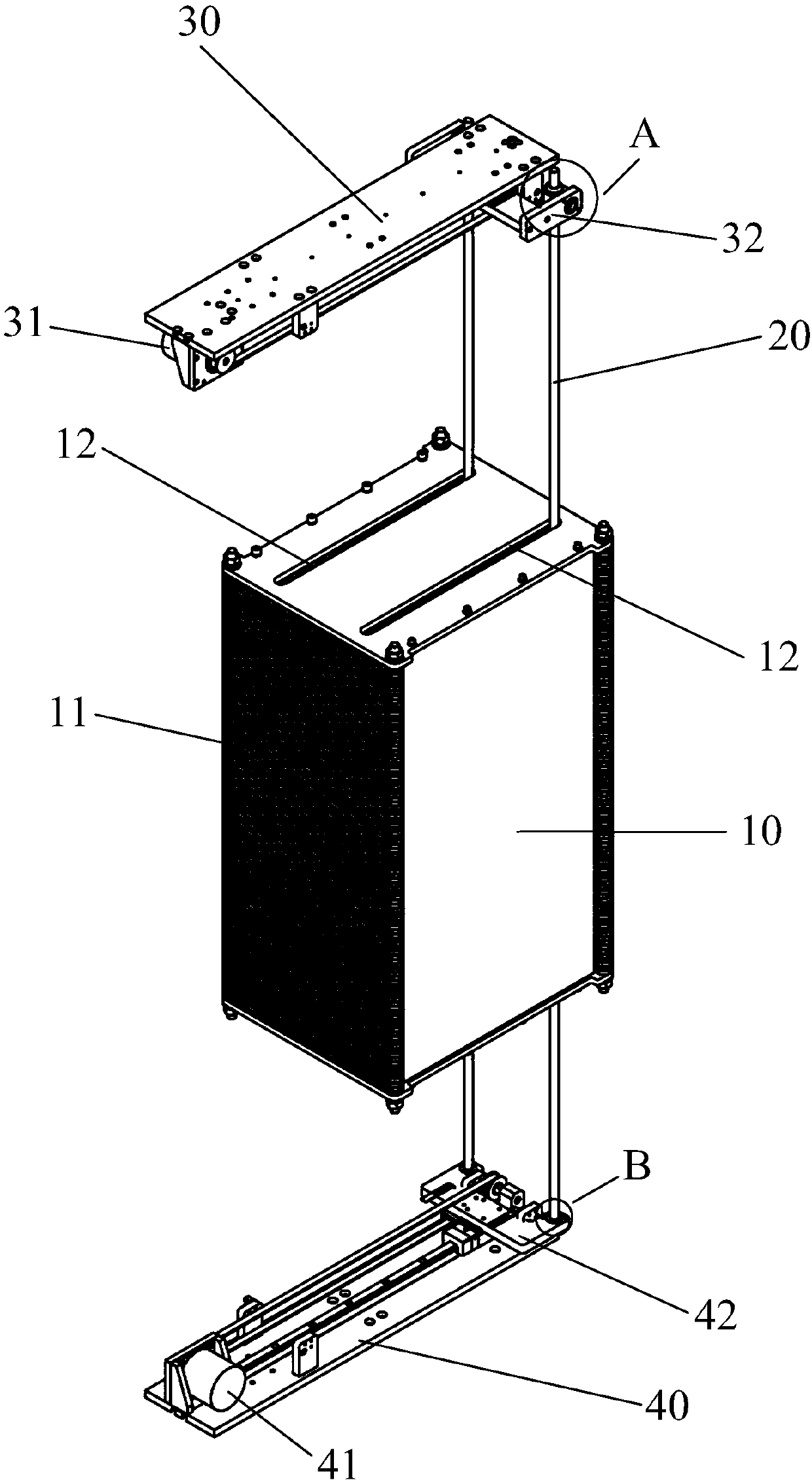
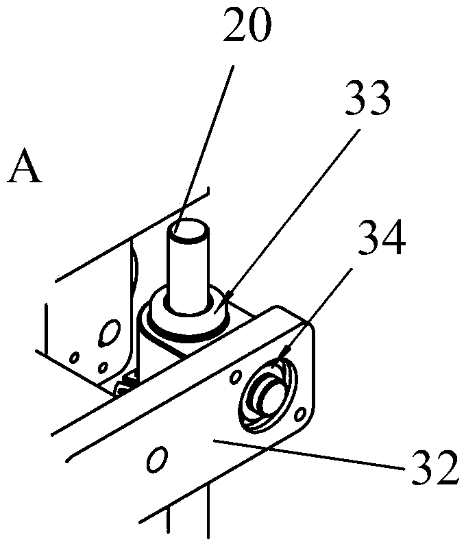
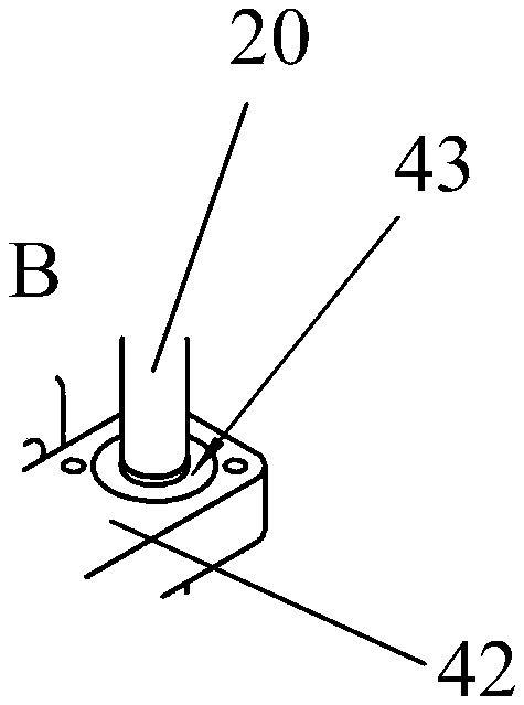
[0024] Please refer to figure 1 , figure 1 It is a structural schematic diagram of a specific embodiment of the paper pushing mechanism according to the pre...


PUM


Abstract

The invention provides a paper pushing mechanism. The paper pushing mechanism comprises a temporary storage part, at least one push rod, a first push rod driving part and a second push rod driving part, wherein the temporary storage part comprises a plurality of temporary storage cavities, each temporary storage cavity is used for storing one or more paper documents, and limiting penetrating slotsare formed in the temporary storage cavity shells; the push rods are arranged in the limiting penetrating slots and stretch and penetrate the temporary storage cavities; one ends of the push rods areconnected to the first push rod driving part through first connecting parts and the other ends of the push rods are connected to the second push rod driving part through second connecting parts, andthe push rods rotate angularly by taking the first connecting parts and / or the second connecting parts as a center of circle; and the first push rod driving part drives the first connecting parts to move and the second push rod driving part drives the second connecting parts to move homonymously relative to the first connecting parts so as to drive the push rods to move along the limiting penetrating slots.

Description

technical field [0001] The invention relates to the field of office automation equipment, in particular to a paper pushing mechanism. Background technique [0002] In the existing field of automatic paper processing, automatic paper sorting is often used to sort a stack of disordered paper according to expectations, so as to facilitate subsequent file filing. In a typical application scenario, the sorted papers are temporarily stored in different chambers, and the process of taking papers out of the chambers into stacks requires manual intervention. Due to the limited size of the cavity, the method of manually picking up paper is cumbersome, which increases the workload of the staff, and is also prone to bending and damage of the paper due to improper manual control. Therefore, people expect to provide a suitable mechanical structure for this scene, so as to realize quick and convenient paper taking. Contents of the invention [0003] In order to overcome the above-menti...

Claims


Application Information

Patent Timeline
IPC IPC(8): B65H31/30
CPCB65H31/3081
Inventor 王小飞欧智华刘孟明
Owner 北京太章机电设备有限公司
Why Eureka
Try Eureka