OLED light source driving control circuit and OLED lamp

A control circuit and light source driving technology, applied in the direction of electrical components, etc., can solve problems such as low driving efficiency, poor EMC anti-interference ability, and complicated wiring harness, so as to improve circuit conversion efficiency, reduce power consumption and heat, and reduce drive. The effect of plate area

Pending Publication Date: 2020-03-20
HASCO VISION TECHNOLOGY CO LTD
View PDF1 Cites 1 Cited by
  • Summary
  • Abstract
  • Description
  • Claims
  • Application Information

AI Technical Summary

Problems solved by technology

This driving method has low driving efficiency, occupies more IO ports of single-chip microcomputer resources, and has complicated wiring harnesses, which is not conducive to scalability and platformization.
Moreover, the EMC anti-interference ability is poor. When there is strong electromagnetic interference from the outside world, the OLED drive and control circuit is easily disturbed, causing the OLED to emit light abnormally.

Method used


Image

  • OLED light source driving control circuit and OLED lamp
  • OLED light source driving control circuit and OLED lamp
  • OLED light source driving control circuit and OLED lamp

Examples


Embodiment Construction

[0052] Embodiments of the present invention are described below through specific examples, and those skilled in the art can easily understand other advantages and effects of the present invention from the content disclosed in this specification. The present invention can also be implemented or applied through other different specific implementation modes, and various modifications or changes can be made to the details in this specification based on different viewpoints and applications without departing from the spirit of the present invention. It should be noted that, in the case of no conflict, the following embodiments and features in the embodiments can be combined with each other.

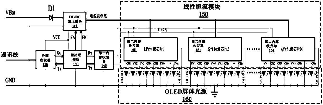
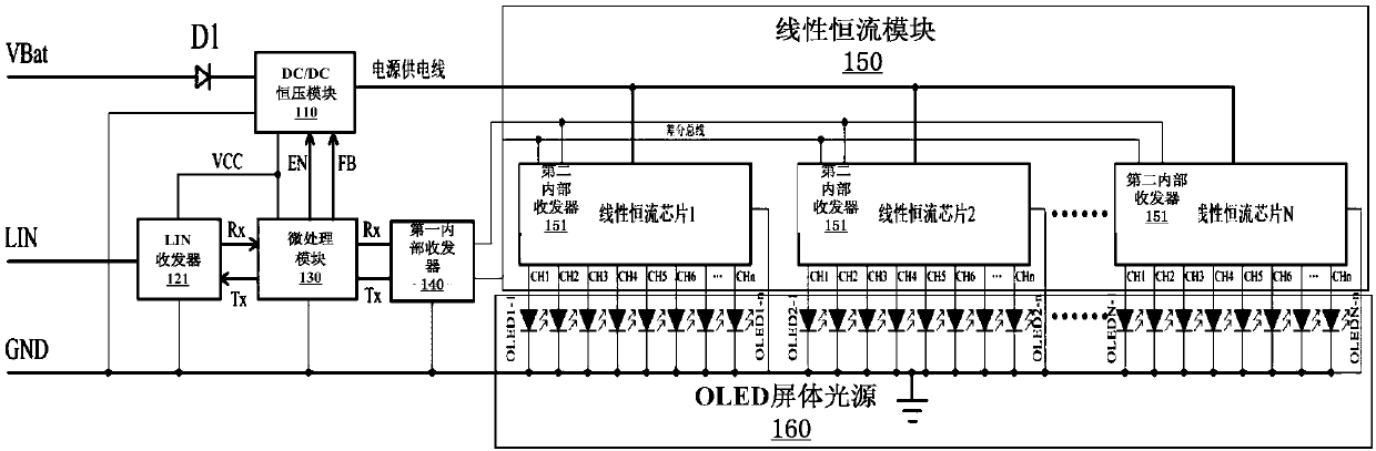
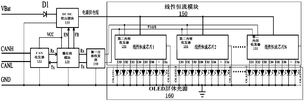
[0053] see Figure 1 to Figure 1 3. It should be noted that the structures, proportions, sizes, etc. shown in the drawings attached to this specification are only used to match the content disclosed in the specification, for those who are familiar with this technology to understand and read, ...


PUM


Abstract

The invention provides an OLED light source drive control circuit and an OLED lamp. The drive control circuit comprises a DC / DC constant voltage module, an external transceiver, a first internal transceiver, a micro-processing module, a linear constant current module and an OLED screen body light source. The micro-processing module communicates with the first internal transceiver, feeds back the detected output voltage to the DC / DC constant-voltage module and controls the DC / DC constant-voltage module to work; the first internal transceiver is connected with the linear constant-current modulethrough a differential bus; the linear constant-current module comprises a plurality of linear constant-current chips, each linear constant-current chip is provided with a second internal transceiver,and differential bus interfaces of the second internal transceivers are connected to differential bus communication lines connected with the differential bus interfaces of the first internal transceivers respectively. According to the invention, the anti-interference capability is stronger, and the circuit conversion efficiency of the whole driving system is effectively improved.

Description

technical field [0001] The invention relates to the technical field of automobile lamps, in particular to the technical field of automotive OLED lamps, in particular to an OLED light source drive control circuit and an OLED lamp. Background technique [0002] As the preferred light source for automotive signal lights, LEDs have been widely and maturely used in automotive signal lights with various functions. However, as a point light source, LEDs are used as a signal light with a certain function in the rear lights of automobiles. Generally, multiple LEDs are required to realize a function. The luminous effect of multiple LEDs does not depend on the use of a good optical reflection system and a light distribution mirror. , it is difficult to achieve good luminous uniformity. Organic light-emitting diode (OLED) products have two major advantages: on the one hand, their self-illuminating characteristics do not require the support of any light source system, and the thickness ...

Claims


Application Information

Patent Timeline
Patent Type & Authority Applications(China)
IPC IPC(8): H05B45/30
Inventor 李佳颖
Owner HASCO VISION TECHNOLOGY CO LTD
Why Eureka
Try Eureka