A pneumatic balance crane cylinder mechanism

A technology of pneumatic balance crane and balance cylinder, which is applied in the direction of clockwork mechanism and hoisting device, can solve the problems of reduced service life of balance crane, damage of balance crane, and reduced service life of balance crane, so as to achieve small impact, The effect of improving the service life

Active Publication Date: 2021-07-30
TAIZHOU XINGDAO MACHINERY MFG
View PDF0 Cites 0 Cited by
  • Summary
  • Abstract
  • Description
  • Claims
  • Application Information

AI Technical Summary

Problems solved by technology

[0004] However, when the existing cylinder mechanism is working, when the steel wire rope for hanging the heavy object rises with no load, the speed will become faster and faster, resulting in excessive internal impact on the balance cylinder, which will easily cause damage to the balance crane and reduce the balance. The service life of the crane, and when the pressure is released on the mount, the pressure on the side of the piston plate 4 drops sharply, and the speed of the piston plate 4 and the reel 5 moving to the right is also getting faster and faster, which also causes an impact on the inside of the balance cylinder, making the balance crane reduced service life

Method used


Image

  • A pneumatic balance crane cylinder mechanism
  • A pneumatic balance crane cylinder mechanism
  • A pneumatic balance crane cylinder mechanism

Examples


Embodiment Construction

[0016] The following will clearly and completely describe the technical solutions in the embodiments of the present invention with reference to the accompanying drawings in the embodiments of the present invention. Obviously, the described embodiments are only some, not all, embodiments of the present invention. Based on the embodiments of the present invention, all other embodiments obtained by persons of ordinary skill in the art without making creative efforts belong to the protection scope of the present invention.

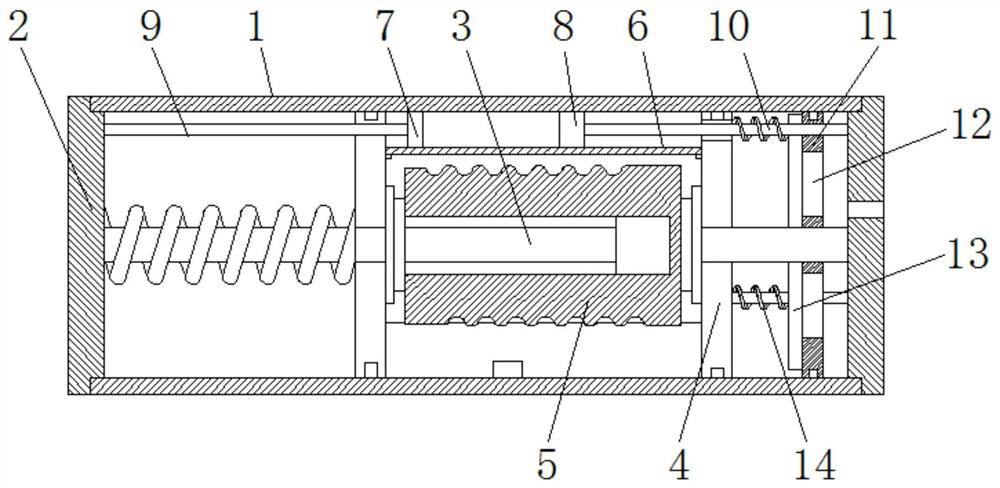
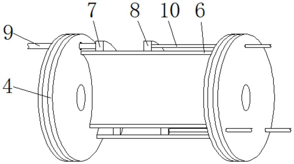
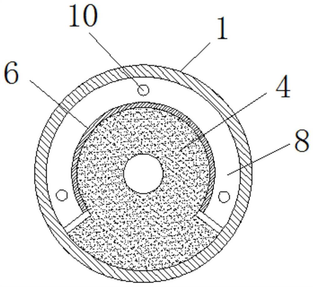
[0017] see Figure 1-3 , a pneumatic balance crane cylinder mechanism, including a balance cylinder 1, a support side plate 2, a ball screw 3, a piston plate 4, and a cable reel 5, and both sides of the balance cylinder 1 are fixedly connected with a support side plate 2 by screws , the middle part between the two supporting side plates 2 is equipped with a ball screw 3, and the ball screw 3 is movably sleeved with two piston plates 4, and the side of a piston...


PUM


Abstract

The invention relates to the field of balance crane equipment, and discloses a pneumatic balance crane cylinder mechanism, which includes a balance cylinder, a support side plate, a ball screw, a piston plate, and a cable reel, and both sides of the balance cylinder are provided with support side plates , a ball screw is arranged between the two supporting side plates, and a piston plate and a cable reel are arranged on the ball screw. The pneumatic balance crane cylinder mechanism, through the design of the supporting side plates on both sides of the cable drum, cooperates with the sealing plate, the first sealing plate, the second sealing plate, the first fixed shaft, the second fixed shaft, the moving sealing plate and the sealing When the balance crane moves upwards with no load, a negative pressure is formed between the first sealing plate and the piston plate on the right side of the cable drum, and the negative pressure increases as the cable drum continues to move, and the limit line The leftward movement of the cable drum makes the balance crane gradually tend to a stable state when it moves up with no load, which makes the balance crane less impacted and improves the service life of the balance crane.

Description

technical field [0001] The invention relates to the field of balance crane equipment, in particular to a pneumatic balance crane cylinder mechanism. Background technique [0002] The pneumatic balance crane is a pneumatic handling device that uses the gravity of the heavy object and the pressure in the cylinder to achieve balance to lift or lower the heavy object. Generally, a pneumatic balance crane has two balance points, which are heavy load balance and no-load balance. The gripper will always be at rest. At this time, only a small external force can be used to lift or lower the heavy object or gripper, which improves work efficiency and reduces labor intensity of workers. The pneumatic balance crane includes inflatable equipment, reversing valves, and cylinder mechanisms. and other components. [0003] Existing cylinder mechanism comprises balance cylinder 1, support side plate 2, ball screw mandrel 3, piston plate 4 and cable reel 5, when working (refer to Figure 4 ):...

Claims


Application Information

Patent Timeline
Patent Type & Authority Patents(China)
IPC IPC(8): B66D1/08B66D1/14B66D1/28
CPCB66D1/08B66D1/14B66D1/28
Inventor 康林科
Owner TAIZHOU XINGDAO MACHINERY MFG
Why Eureka
Try Eureka