Compressor and refrigeration circulating system with same

A technology of compressors and cylinders, applied in the field of compressors, can solve the problems of large contact area, high cost, small diameter, etc., and achieve the effect of simple matching, easy processing, and tight matching

Active Publication Date: 2020-04-28
GUANGDONG MEIZHI PRECISION MFG
View PDF5 Cites 0 Cited by
  • Summary
  • Abstract
  • Description
  • Claims
  • Application Information

AI Technical Summary

Problems solved by technology

[0002] The compression mechanism of the compressor in the related art cooperates the piston and the sliding vane in a hinged manner. In this matching mode, the processing accuracy of the fitting groove on the head of the sliding vane and the piston is very high, and at the same time, due to its large height , but the diameter is very small, the processing is difficult, the time required to process a single workpiece is long, the cost is high, and it cannot meet the needs of large-scale mass production, and there is still a gap between the head of the slide plate and the matching groove on the piston. During the operation of the machine, the sliding plate and the piston will still collide, resulting in a large noise. In addition, due to the large contact area between the two, the friction power consumption is also large.

Method used


Image

  • Compressor and refrigeration circulating system with same
  • Compressor and refrigeration circulating system with same
  • Compressor and refrigeration circulating system with same

Examples


Embodiment Construction

[0055] Embodiments of the present invention are described in detail below, examples of which are shown in the drawings, wherein the same or similar reference numerals designate the same or similar elements or elements having the same or similar functions throughout. The embodiments described below by referring to the figures are exemplary only for explaining the present invention and should not be construed as limiting the present invention.

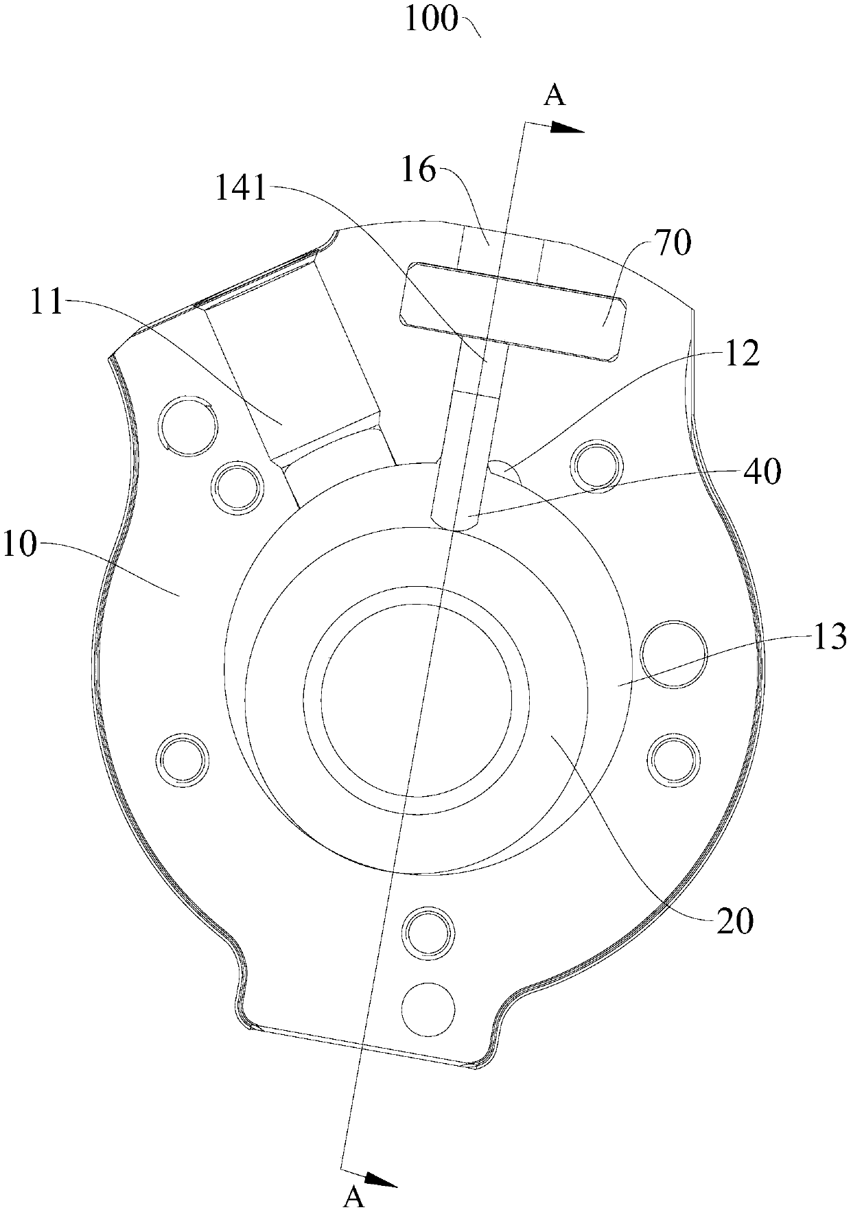
[0056] Refer below Figure 3-Figure 17 The compressor 100 according to the embodiment of the first aspect of the present invention is described. The compressor 100 includes a housing compression member and a motor, wherein the compression member and the motor are located in the housing, and the motor is used to drive the crankshaft 30 of the compression member.

[0057] Such as image 3 and Figure 4 As shown, the compressor 100 according to the embodiment of the present invention includes a cylinder 10 , a piston 20 , a crankshaft 30 ...


PUM


Abstract

The invention discloses a compressor and a refrigeration circulating system with the compressor. The compressor comprises an air cylinder, a piston, a crankshaft, a slip sheet, a main bearing, an auxiliary bearing and a valve module, wherein the air cylinder has a first air suction port and a first exhaust port, an air cylinder hole connecting the first air suction port and the first exhaust portis defined in the air cylinder, the air cylinder is provided with a sliding groove communicating with the air cylinder hole, the air cylinder is provided with an air valve groove in the radial extension direction of the sliding groove, and the air valve groove is located on the radial outer side of the sliding groove; the piston can be arranged in the air cylinder hole in an eccentric and rotatingmanner and has a center hole; the crankshaft is provided with an eccentric shaft, and the eccentric shaft is arranged in the center hole in a penetrating manner; the slip sheet can be arranged in thesliding groove in a sliding manner, the end, facing the piston, of the slip sheet abuts against the piston, and a step part is arranged at the end, away from the piston, of the slip sheet; the main bearing and the auxiliary bearing are arranged on the crankshaft in a sleeving manner and located on the upper side and the lower side of the air cylinder; and the valve module is arranged in the air valve groove, and a second working chamber is defined by at least one of the main bearing and the auxiliary bearing, together with the valve module, the step part and the air cylinder. The compressor is easy and convenient to machine, low in cost, close in cooperation and low in power consumption.

Description

technical field [0001] The invention relates to the technical field of compressors, in particular to a compressor and a refrigeration cycle system with the same. Background technique [0002] The compression mechanism of the compressor in the related art cooperates the piston and the sliding vane in a hinged manner. In this matching mode, the processing accuracy of the fitting groove on the head of the sliding vane and the piston is very high, and at the same time, due to its large height , but the diameter is very small, the processing is difficult, the time required to process a single workpiece is long, the cost is high, and it cannot meet the needs of large-scale mass production, and there is still a gap between the head of the slide plate and the matching groove on the piston. During the operation of the machine, the sliding plate and the piston will still collide, which will generate a lot of noise. In addition, due to the large contact area between the two, the fricti...

Claims


Application Information

Patent Timeline
IPC IPC(8): F04C18/356F04C29/12F04C29/00
CPCF04C18/3564F04C29/00F04C29/124F04C2240/20
Inventor 宋鹏杰吴延平
Owner GUANGDONG MEIZHI PRECISION MFG
Why Eureka
Try Eureka