Emergency release device

A technology of emergency release and mounting seat, which is applied in the field of emergency release, and can solve problems such as damaged joints, reduced safety, and personnel injury, and achieves the effects of reliable emergency release, high reliability, and convenient use

Active Publication Date: 2020-05-08
XIAN AIRCRAFT DESIGN INST OF AVIATION IND OF CHINA
View PDF10 Cites 1 Cited by
  • Summary
  • Abstract
  • Description
  • Claims
  • Application Information

AI Technical Summary

Problems solved by technology

[0002] In terms of emergency release of the rope, there are many structural forms at home and abroad, generally bolted or fastened. When emergency release is required, hard damage is used to achieve separation, which destroys the connection, and the release is easy to cause damage under external force. People are injured, safety is reduced, the cost is relatively high, the economy is poor, and it is easy to be restricted by external conditions

Method used


Image

  • Emergency release device
  • Emergency release device
  • Emergency release device

Examples


Embodiment Construction

[0012] Below in conjunction with accompanying drawing, the present invention is described in further detail:

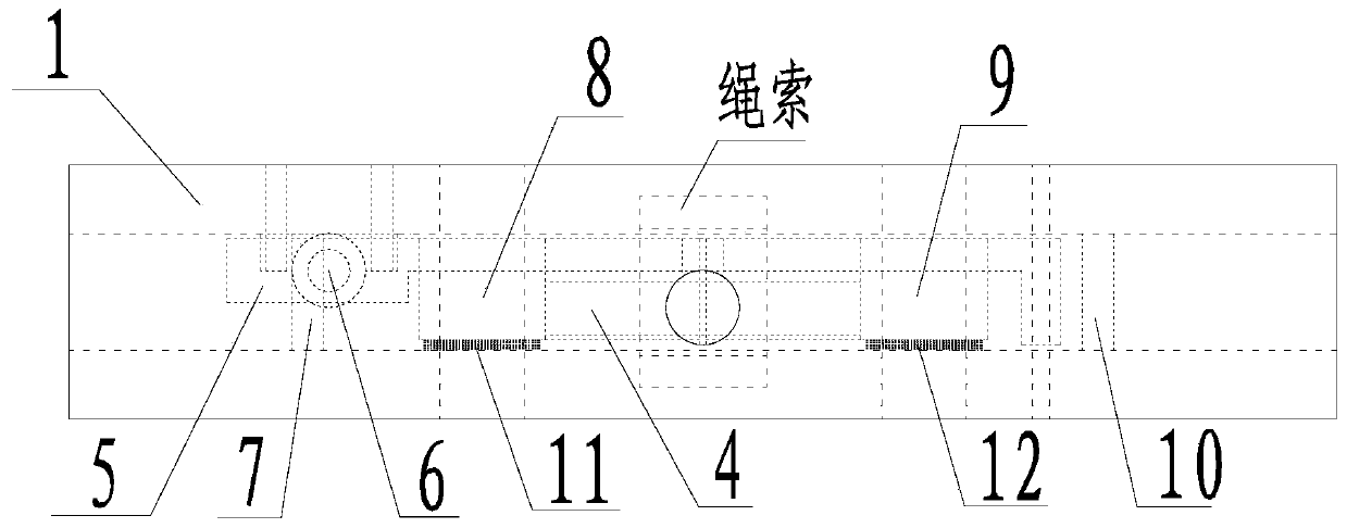
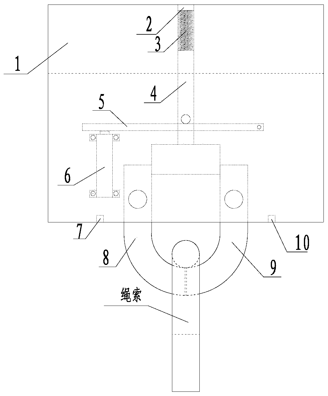
[0013] Such as figure 1 , 2 As shown, an emergency release device includes a mounting seat 1, a blocking cover 2, a compression spring 3, a limit rod 4, a rotating rod 5, a high-pressure gas cylinder 6, a left limit block 7, a left arc-shaped hook 8, Right arc-shaped hook 9, right stop block 10, left torsion spring 11 and right torsion spring 12 are combined. Wherein, the mounting base 1 is a rectangular body, the lower surface of the mounting base 1 has a rectangular groove upwards and the left and right sides communicate with each other, the middle part of the upper surface of the mounting base 1 has a circular through hole downwards and communicates with the rectangular groove, and the limit rod 4 The upper and middle parts are cylindrical, the lower part is rectangular, and a circular boss protrudes from the middle of the limit rod 4. The upper part of the limit...


PUM


Abstract

The invention relates to the field of emergency release, in particular to an emergency release device. The device comprises a mounting base (1), a blocking cover (2), a compressed spring (3), a limiting rod (4),a rotary rod (5), a high-pressure gas actuator cylinder (6), a left limiting block (7), a left arc-shaped hook (8), a right arc-shaped hook (9), a right limiting block (10), a left torsional spring (11) and a right torsional spring (12). According to the emergency release device, a rope emergency release part is arranged in the simple device in an integrated manner, the cost is reduced,the reliability is high, and it is achieved that equipment or ropes are released safely and reliability in emergency. The emergency release device is simple, solid, and convenient to use without limitation caused by the outside world.

Description

technical field [0001] The invention relates to the technical field of emergency release, in particular to an emergency release device. Background technique [0002] In terms of emergency release of the rope, there are many structural forms at home and abroad, generally bolted or fastened. When emergency release is required, hard damage is used to achieve separation, which destroys the connection, and the release is easy to cause damage under external force. People are injured, safety is reduced, the cost is relatively high, the economy is poor, and it is easily restricted by external conditions. Contents of the invention [0003] The purpose of the present invention is: [0004] The invention provides an emergency release device for emergency release of equipment or ropes, which is suitable for safe and reliable emergency release of equipment or ropes. [0005] Technical scheme of the present invention is: [0006] An emergency release device, including a mounting seat...

Claims


Application Information

Patent Timeline
Patent Type & Authority Applications(China)
IPC IPC(8): A62B35/00
CPCA62B35/0075
Inventor 张恒铭
Owner XIAN AIRCRAFT DESIGN INST OF AVIATION IND OF CHINA
Why Eureka
Try Eureka