A safety release mechanism with locking and emergency fixed force

A fixed force and safe technology, applied in the direction of quick-acting fasteners, etc., can solve the problems of poor economy, complex structure, inconvenient operation, etc., and achieve the effects of high reliability, low cost and convenient use.

Active Publication Date: 2018-01-16
XIAN AIRCRAFT DESIGN INST OF AVIATION IND OF CHINA
View PDF5 Cites 0 Cited by
  • Summary
  • Abstract
  • Description
  • Claims
  • Application Information

AI Technical Summary

Problems solved by technology

Therefore, the operation is not convenient enough, and two mechanisms are used to realize the locking and emergency fixed force safety release, and the structure is too complicated to realize the set safety separation load
The cost is relatively high, the economy is poor, and it is easily restricted by external conditions

Method used


Image

  • A safety release mechanism with locking and emergency fixed force
  • A safety release mechanism with locking and emergency fixed force
  • A safety release mechanism with locking and emergency fixed force

Examples


Embodiment Construction

[0014] Below in conjunction with accompanying drawing, the present invention is described in further detail:

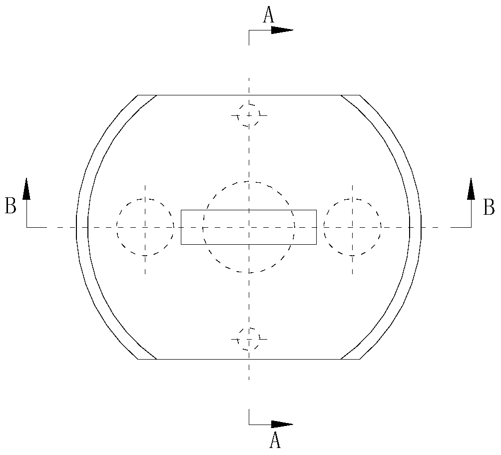
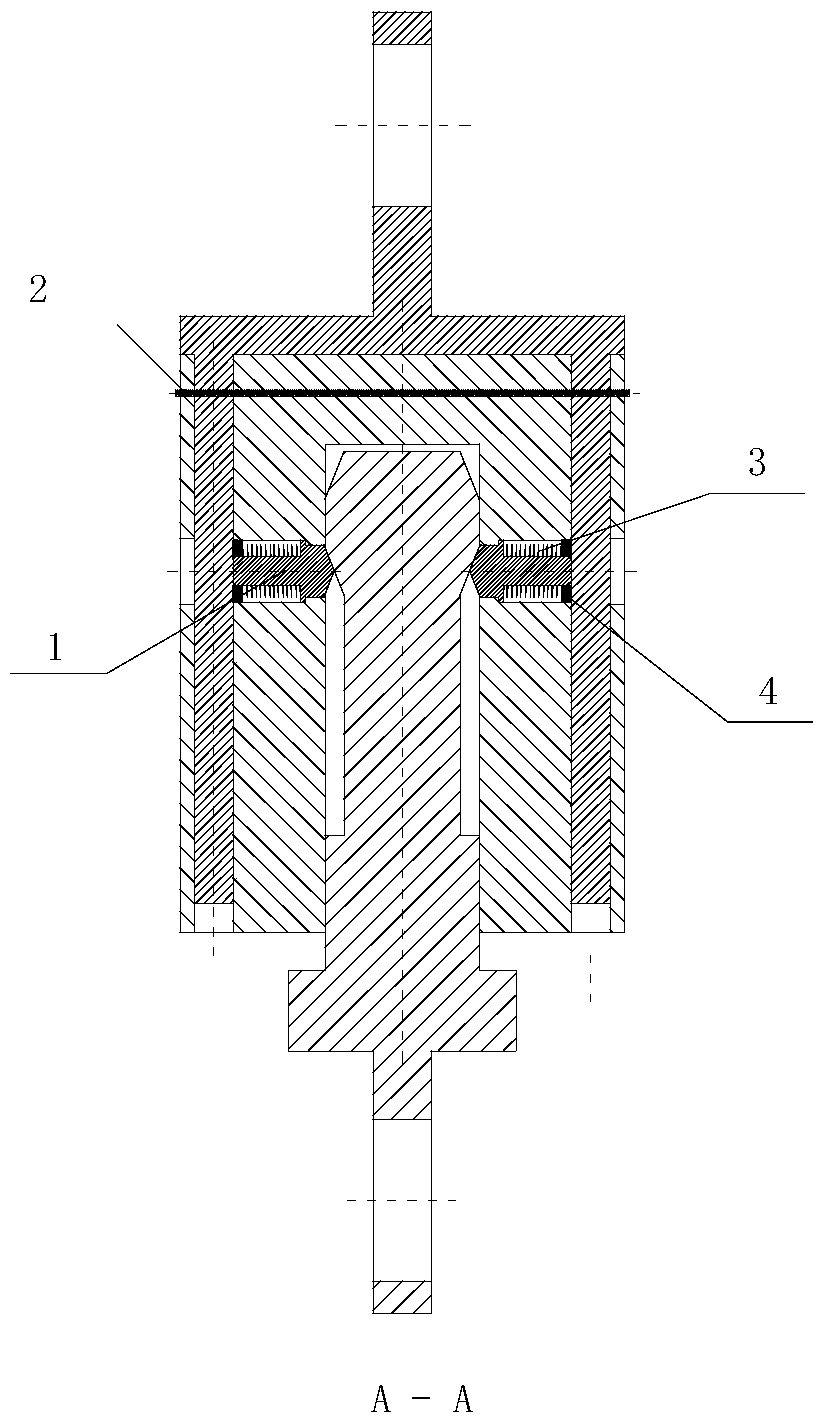
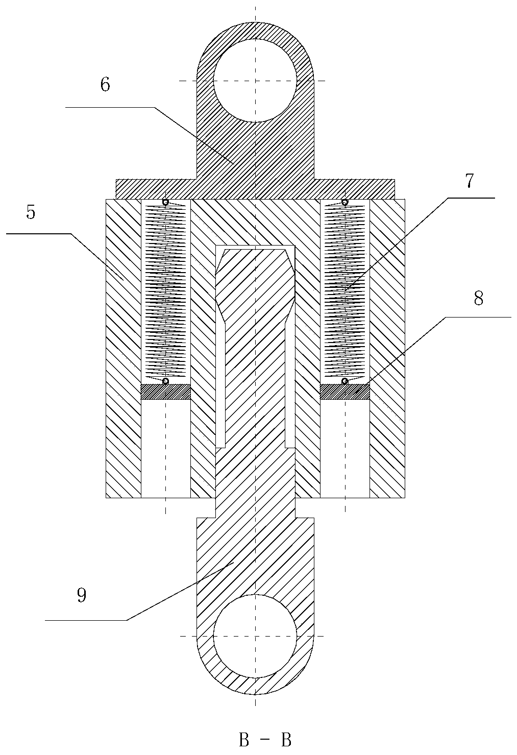
[0015] A safety release mechanism with locking and emergency fixed force, such as figure 1 , 2 , 3, including slider 1, locking pin 2, pressure spring 3, blocking cover 4, connecting piece 5, mounting seat 6, tension spring 7, constant force block 8, and separating piece 9;

[0016] Wherein, there are 5 circular holes upwards on the lower surface of the connector 5, and the 5 circular holes are distributed in a cross, wherein the central circular hole is a blind hole, and the remaining 4 holes are through holes; the top of the mounting seat 6 is a connecting part, and the mounting Two cantilever rods are symmetrically distributed front and back under the seat 6, and the cantilever rods extend into the front and rear 2 round holes of the connector 5, and two tension springs 7 are symmetrically arranged under the mounting seat 6, and each tension spring 7 lower end is ...


PUM


Abstract

The invention relates to the technical field of safe separation of equipment, in particular to a safety detachment mechanism with locking and emergency constant force. This mechanism includes a slider (1), a locking pin (2), a compression spring (3), a blocking cover (4), a connector (5), a mounting seat (6), a tension spring (7), and a fixed force block (8 ), separate parts (9). The invention integrates locking and emergency fixed force safe release into one simple mechanism, reduces cost, has high reliability, and realizes equipment locking and emergency fixed force safe release. The mechanism is simple, firm, highly reliable, easy to use, and not restricted by external conditions.

Description

technical field [0001] The invention relates to the technical field of safe separation of equipment, in particular to a safety detachment mechanism with locking and emergency constant force. Background technique [0002] In terms of locking and emergency detachment, there are many structural forms at home and abroad. Generally, there are only mechanisms with locking and release functions, or mechanisms with emergency detachment functions. Mechanisms with emergency detachment functions generally use the method of destroying connectors for emergency detachment. Therefore, the operation is not convenient enough, and two mechanisms are used to realize locking and emergency fixed force safety release, and the structure is too complicated to realize setting safety separation load. The cost is relatively high, the economy is poor, and it is easily restricted by external conditions. Contents of the invention [0003] The purpose of the present invention is: [0004] The inventio...

Claims


Application Information

Patent Timeline
Patent Type & Authority Patents(China)
IPC IPC(8): F16B21/08
Inventor 张恒铭崔小航马肖杰
Owner XIAN AIRCRAFT DESIGN INST OF AVIATION IND OF CHINA
Why Eureka
Try Eureka