Cutting device accessory for special optical fiber, cutting device and optical fiber cutting method

A technology of cutting device and special optical fiber, applied in the field of cutting device and optical fiber cutting, can solve the problems of unguaranteed, smooth end face without tailing, difficult to ensure cutting effect, etc., and achieve the effect of small cutting angle and high repeatability

Pending Publication Date: 2020-05-08
CHINA WEAPON EQUIP RES INST
View PDF0 Cites 3 Cited by
  • Summary
  • Abstract
  • Description
  • Claims
  • Application Information

AI Technical Summary

Problems solved by technology

The general requirement is that the cutting angle error is small when viewed from the side after cutting, and the end face is observed to be flat without tailing or edge (crash), especially in the process of optical fiber fusion, when the cutting angle is greater than 0.7° or the diameter of the stress zone is more than 20%. Tail, can not meet the requirements of high-quality welding
[0004] The existing optical fiber cutting equipment can already handle ordinary double-clad optical fibers, such as GDF-20 / 400, etc. in the process of processing, but when processing panda-shaped optical fibers, octagonal optical fibers, bow-tie optical fibers, and a For special optical fibers such as font-shaped optical fibers and photonic crystal optical fibers, the cutting effect is often not satisfactory, and it is difficult to obtain a good and stable cutting effect, and it is impossible to achieve high-quality and high-repeatability cutting
[0005] For example, the current mainstream suppliers of optical fiber cutting equipment, when cutting polarization-maintaining optical fibers or other special optical fibers, the same tensile force cannot guarantee various axial angles (such as cat's eye position 0°, 15°, 25°...) The end surface is flat and no tailing when cutting
Therefore, it is difficult to ensure the cutting effect

Method used


Image

  • Cutting device accessory for special optical fiber, cutting device and optical fiber cutting method
  • Cutting device accessory for special optical fiber, cutting device and optical fiber cutting method
  • Cutting device accessory for special optical fiber, cutting device and optical fiber cutting method

Examples


Embodiment 1

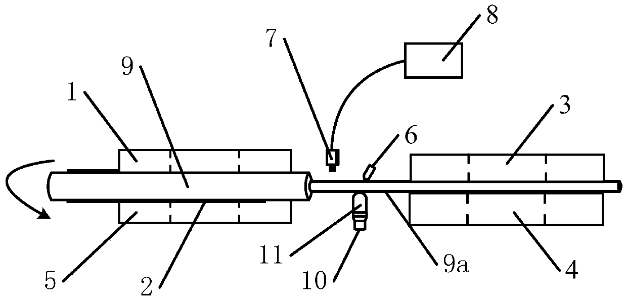
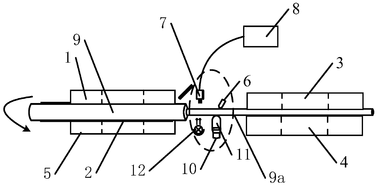
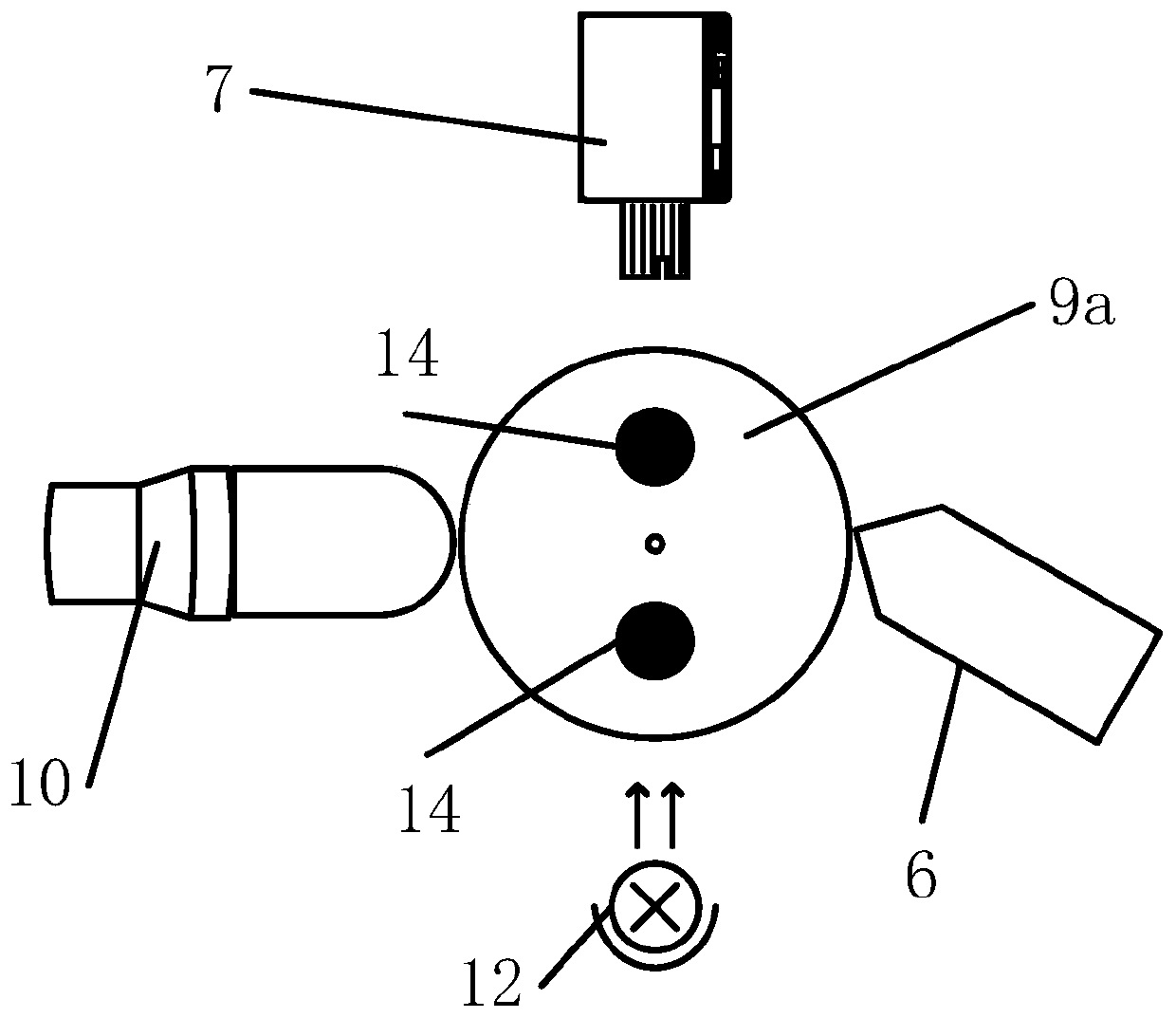
[0097] like figure 1 The cutting device in the shown optical fiber cutting equipment may include a left upper cover (the first upper cover 1), a clamp 2, a right upper cover (the second upper cover 3), and a right lower cover ( The second lower cover plate 4), the left lower cover plate (the second lower cover plate 5), cutting knife (knife 6), digital microscope (visual observation device 7), display 8, optical fiber to be cut (including Coated optical fiber segment 9 and optical fiber segment 9a) after stripping the coating layer, brake (piezoelectric actuator 10), top pressure block 11 (cylindrical top block) and the like. Among them, the jig can use Vytran's 3600 fusion splicer transfer jig, the diameter of the fiber groove of the jig matches the fiber to be cut, if the diameter of the fiber coating layer is 550 microns, the transfer jig should be 500 type; the cutting knife can be a diamond cutting blade; digital The microscope can use the super eye B11+L1000 lens; the o...

Embodiment 2

[0101] The microscope in the scheme can also adopt a visual optical microscope, which can directly observe the side of the optical fiber by visual observation, and is used to evaluate the rotation of the optical fiber to a specific position, and the same cutting effect as that in Example 1 can be obtained. Other configurations are the same as in Embodiment 1.

Embodiment 3

[0103] In the solution, the optical fiber is replaced with an octagonal optical fiber, and the optical fiber is rotated to a symmetrical position. Other configurations are the same as those in Embodiment 1, and the same cutting effect as in Embodiment 1 can be obtained.


PUM


Abstract

The invention provides a cutting device accessory for a special optical fiber, a cutting device and an optical fiber cutting method. The cutting device accessory comprises a clamp, a visual observation device, a jacking and breaking device and an adjustable translation table. The clamp is used for being installed in a groove, parallel to an optical fiber placing direction, of a one-dimensional translation table of the cutting device in a detachable mode and used for clamping and locking one end of a to-be-cut optical fiber. The visual observation device is mounted on a lifting adjusting frameof the adjustable translation table and is used for observing a to-be-cut part of a to-be-cut optical fiber; the jacking and breaking device comprises a jacking and pressing block and an actuator usedfor driving the jacking and pressing block to apply a jacking and pressing force to a to-be-cut optical fiber. The jacking and pressing block is installed on the moving part of the actuator and usedfor jacking a pre-cutting position of the to-be-cut optical fiber after the to-be-cut optical fiber is pre-cut by a cutter of the cutting device so that the to-be-cut optical fiber can be broken. According to the scheme, the cutting end surface of the optical fiber is smooth without trailing.

Description

technical field [0001] The invention relates to the field of communication wire processing and construction equipment, and more specifically, the invention relates to a cutting device accessory for a special optical fiber, a cutting device and an optical fiber cutting method. Background technique [0002] A very important step before fiber splicing is fiber cutting, which has a great influence on the splicing strength and splicing loss. For very thin optical fibers, the end of the cut optical fiber is still flat after hundreds of times of magnification, so it can be used for device packaging, cold splicing, and spark fusion splicing. [0003] In the cutting process of the prior art, a diamond cutting knife is usually used to create a microcrack on the surface of the optical fiber, and the optical fiber is split by the tension applied to the optical fiber to obtain a high-quality cutting effect. When cutting the optical fiber with a cutter, use the cutter to cut the optical ...

Claims


Application Information

Patent Timeline
Patent Type & Authority Applications(China)
IPC IPC(8): G02B6/25
CPCG02B6/25
Inventor 李川
Owner CHINA WEAPON EQUIP RES INST
Why Eureka
Try Eureka