High-strength structure warp beam assembly for warp knitting machine

A high-strength, warp knitting machine technology, applied in warp knitting, textiles, papermaking, knitting, etc., can solve the problem of lack of clamping effect of yarn loops, and achieve convenient weaving, disassembly, replacement and maintenance, high strength big effect

Active Publication Date: 2020-05-12
FUJIAN HANGGANG TEXTILE TECH CO LTD
View PDF9 Cites 3 Cited by
  • Summary
  • Abstract
  • Description
  • Claims
  • Application Information

AI Technical Summary

Problems solved by technology

[0004] However, the pan head in this utility model patent lacks the problem of clamping the yarn coil

Method used


Image

  • High-strength structure warp beam assembly for warp knitting machine
  • High-strength structure warp beam assembly for warp knitting machine
  • High-strength structure warp beam assembly for warp knitting machine

Examples


Embodiment

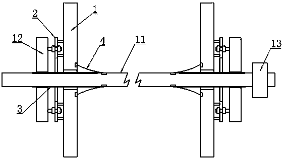
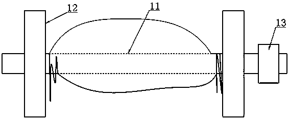
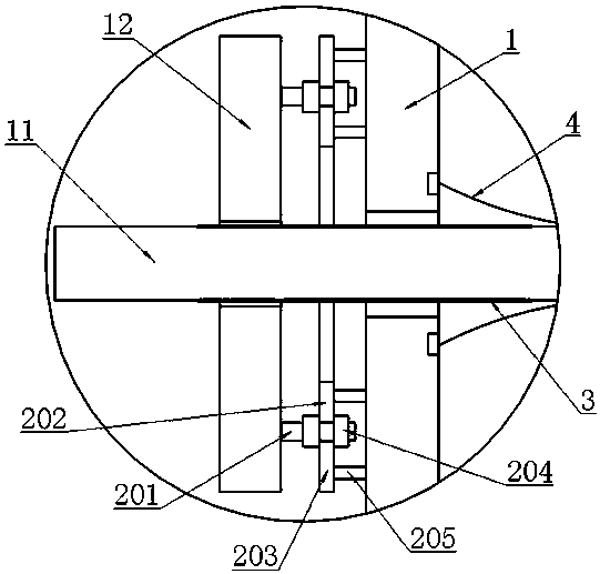
[0025] Example: as attached figure 1 , 2 , 3, 4, 5, 6 and attached Figure 7 As shown, a high-strength warp beam assembly for a warp knitting machine includes a shaft body 11, two end plates 12 arranged on the shaft body 11, and a driving gear 13 arranged on the shaft body 11 , also includes a clamping ring 1 sleeved on the shaft body 11 and located inside the end plate 12, set on the opposite sides of the end plate 12 and the clamping ring 1 and used to lift the The jacking unit 2 of the clamping ring 1 is arranged at both ends of the shaft body 11 and is respectively used for screwing and installing the shaft body threaded section 3 of the end plate 12 with an internally threaded hole, and the two sides are respectively arranged at The inner surface of the clamping ring 1 and the annular surface of the shaft body 11 are used to cover the threaded section 3 of the shaft body and protect the cylindrical elastic sleeve unit 4 of the yarn.

[0026] In this embodiment, when th...


PUM


Abstract

The invention belongs to the technical field of structures of warp knitting machines and particularly relates to a high-strength structure warp beam assembly for a warp knitting machine. According tothe high-strength structure warp beam assembly for the warp knitting machine, the effect that the warp beam assembly effectively clamps yarn loops is achieved through the mode that end plates are arranged to be in screw connection and be adjustable, jacking units and clamping rings are arranged on the end plates, and cylindrical elastic sleeve units are arranged between the clamping rings and a shaft body. The warp beam assembly has the advantages that the end plates have clamping and rough adjusting effects on the yarn loops, the clamping rings have clamping and fine adjusting effects on theyarn loops, clamping and adjusting operation is easy and convenient, the clamping structure is large in self-strength, convenient to disassemble, assemble, replace and maintain, threaded sections of he shaft body are prevented from snagging, the yarn loops are not likely to wind mutually or trail on the ground and become dirty or snag and break after being clamped, and the yarn loops are maintained in a compact state all the time and facilitate paying-off knitting.

Description

technical field [0001] The invention belongs to the technical field of warp knitting machine structures, and in particular relates to a high-strength warp shaft assembly for a warp knitting machine. Background technique [0002] The warp beam assembly of the warp knitting machine refers to the shaft assembly at the front end of the warp knitting machine, which is used to pre-wind the yarn and release the yarn in an orderly manner during knitting. Its specific structure mainly includes a shaft body, an end plate and Gear, the method of use is that the yarn is wound on the shaft first, and it is located between two end plates, and then the two ends of the shaft are erected on the frame, and finally the gear is driven by the servo motor to pay off. But on the other hand, when the yarn coil is formed, it will inevitably form a pattern that is thick and dense in the middle, and thin and loose on both sides. At this time, if the end plates on both sides cannot be clamped to the mi...

Claims


Application Information

Patent Timeline
Patent Type & Authority Applications(China)
IPC IPC(8): D04B27/16
CPCD04B27/16
Inventor 黄颢何宏忠胡林辉吴建波
Owner FUJIAN HANGGANG TEXTILE TECH CO LTD
Why Eureka
Try Eureka