Warp beam assembly with high strength structure for warp knitting machine

A high-strength, warp knitting machine technology, used in warp knitting, textiles, papermaking, knitting, etc., can solve problems such as lack of yarn loop clamping

Active Publication Date: 2021-06-04
FUJIAN HANGGANG TEXTILE TECH CO LTD
View PDF9 Cites 0 Cited by
  • Summary
  • Abstract
  • Description
  • Claims
  • Application Information

AI Technical Summary

Problems solved by technology

[0004] However, the pan head in this utility model patent lacks the problem of clamping the yarn coil

Method used


Image

  • Warp beam assembly with high strength structure for warp knitting machine
  • Warp beam assembly with high strength structure for warp knitting machine
  • Warp beam assembly with high strength structure for warp knitting machine

Examples


Embodiment

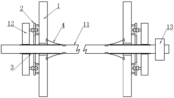
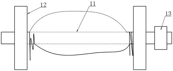
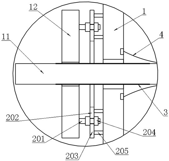
[0025] Example: as attached figure 1 , 2 , 3, 4, 5, 6 and attached Figure 7 As shown, a high-strength warp beam assembly for a warp knitting machine includes a shaft body 11, two end plates 12 arranged on the shaft body 11, and a driving gear 13 arranged on the shaft body 11 , also includes a clamping ring 1 sleeved on the shaft body 11 and located inside the end plate 12, set on the opposite sides of the end plate 12 and the clamping ring 1 and used to lift the The jacking unit 2 of the clamping ring 1 is arranged at both ends of the shaft body 11 and is respectively used for screwing and installing the shaft body threaded section 3 of the end plate 12 with an internally threaded hole, and the two sides are respectively arranged at The inner surface of the clamping ring 1 and the annular surface of the shaft body 11 are used to cover the threaded section 3 of the shaft body and protect the cylindrical elastic sleeve unit 4 of the yarn.

[0026] In this embodiment, when th...


PUM


Abstract

The invention belongs to the technical field of warp knitting machine structures, and in particular relates to a high-strength warp shaft assembly for a warp knitting machine. In the present invention, the end plate is screwed and adjustable, and a jacking unit and a clamping ring are arranged on the end plate, and a cylindrical elastic sleeve unit is arranged between the clamping ring and the shaft body to achieve effective warp beam assembly. The effect of clamping yarn loops. The present invention has the function of clamping the coarse adjustment of the end plate to the yarn coil, the clamping ring has the function of clamping the fine adjustment of the yarn coil, the clamping adjustment operation is simple and convenient, the clamping structure itself has high strength, and is convenient for disassembly, replacement and maintenance. And the threaded section of the shaft body will not snag. After the yarn coils are clamped, it is not easy to entangle with each other, mop the floor dirty, and the hooks will be broken.

Description

technical field [0001] The invention belongs to the technical field of warp knitting machine structures, and in particular relates to a high-strength warp shaft assembly for a warp knitting machine. Background technique [0002] The warp beam assembly of the warp knitting machine refers to the shaft assembly at the front end of the warp knitting machine, which is used to pre-wind the yarn and release the yarn in an orderly manner during knitting. Its specific structure mainly includes a shaft body, an end plate and Gear, the method of use is that the yarn is wound on the shaft first, and it is located between two end plates, and then the two ends of the shaft are erected on the frame, and finally the gear is driven by the servo motor to pay off. But on the other hand, when the yarn coil is formed, it will inevitably form a pattern that is thick and dense in the middle, and thin and loose on both sides. At this time, if the end plates on both sides cannot be clamped to the mi...

Claims


Application Information

Patent Timeline
Patent Type & Authority Patents(China)
IPC IPC(8): D04B27/16
CPCD04B27/16
Inventor 黄颢何宏忠胡林辉吴建波
Owner FUJIAN HANGGANG TEXTILE TECH CO LTD
Why Eureka
Try Eureka