A method for setting up the buffer zone of the UAV control area based on the flight segment based on the collision risk
What is AI technical title?
AI technical title is built by PatSnap AI team. It summarizes the technical point description of the patent document.
A collision risk and buffer zone technology, applied in aircraft traffic control, aircraft navigation/guidance tools, traffic control systems, etc., can solve problems such as lack of scientific basis
Active Publication Date: 2021-02-02
THE SECOND RES INST OF CIVIL AVIATION ADMINISTRATION OF CHINA
View PDF6 Cites 0 Cited by
Summary
Abstract
Description
Claims
Application Information
AI Technical Summary
This helps you quickly interpret patents by identifying the three key elements:
Problems solved by technology
Method used
Benefits of technology
Problems solved by technology
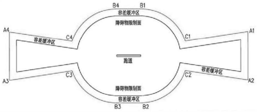
Therefore, it lacks scientific basis for different types of runways to designate different obstacle restriction surfaces but at the same time designate the same tolerance buffer arc radius
Method used
Image
Click on the blue label to locate the original text in one second.
Reading with bidirectional positioning of images and text.
Examples
example 1
[0145] Example 1: Demarcation of control areas under the runway departure procedure of an airport
[0146] Part of the flight segment corresponding to the runway departure procedure is a curve (there is a turn when the flight takes off). The corresponding flight segment in this example s ∈ [0, 10000] is:
[0147]
[0148]
[0149] z(s)=0.05s
[0150] This flight segment describes the turning angle along a circular arc with a radius of 6KM after take-off 2KM Then continue to fly in a straight line. In this example, the parameter of the collision risk zone can be taken as d l = d r = 283.887, d z = 133.5.
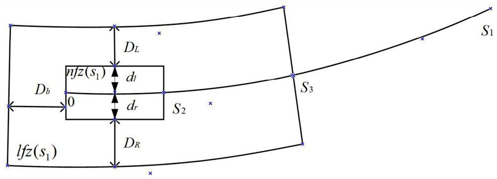
[0151] Suppose h = 120 meters, s 1 =10000 meters, at this moment, the boundary nplane(s of the inner core area of the control area 2 ) corresponding parameter s 2 Satisfy:
[0152] z(s 2 )=h+d z =120+133.5=253.5
[0153] Since the gradient k=0.05 corresponding to the flight segment, so
[0154]
[0155] The control area kernel area nfz(10000) is th...
example 2
[0187] Example 2: Designation of the control area under the approach procedure of an airport runway
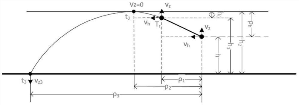
[0188] This example gives an example of the instrument approach procedure of Chongqing Jiangbei Airport RWY02R, the flight is in the final approach segment is a straight line, and the horizontal velocity v can be known according to the information of the instrument approach chart x =93.05m / s, v y = 0m / s, v z =4.9m / s, the descent gradient of the aircraft during the approach phase is
[0189] flight segment s ∈ [0, 10000] satisfies the condition:
[0190] x(s)=s
[0191] y(s)=0
[0192] z(s)=k×s
[0193] Its collision risk zone parameter is d l = d r = 283.887, d z =129.615
[0194] Suppose h = 120 meters, s 1 =10000 meters, at this moment, the boundary nplane(s of the inner core area of the control area 2 ) corresponding parameter s 2 Satisfy:
[0195] z(s 2 )=h+d z =120+129.615=249.615
[0196] Since the gradient k=0.0526 corresponding to the flight seg...
PUM
Abstract
The present invention provides a method for setting up a control area buffer area for a UAV based on a flight segment of collision risk, comprising the following steps: S1, setting a corresponding control area buffer area according to the core area of the control area; S2, a control area buffer area is the minimum area that satisfies the constraints; S3 calculates the buffer parameters of the control area. Through this designation method, the protection range of the inner core area of the control area can be accurately controlled, and the buffer area of the control area can be set up, so as to ensure the accurate designation of the civil UAV control area without affecting the safety and efficiency of civil aircraft operation. It is beneficial to the refined operation management of UAVs.
Description
technical field [0001] The invention relates to the technical field of air traffic control, in particular to the air operation management of unmanned aerial vehicles. Background technique [0002] In recent years, while the scale of the civilian UAV market has continued to expand, due to the fact that UAVs are easy to manufacture, easy to obtain, and have a wide range of users, there are also various risks hidden in the operation of UAVs. Among them, the more typical risks are It interferes with the normal take-off and landing of flights at civil aviation airports. According to statistics, in the two years from 2015 to 2016 alone, there were as many as 27 incidents of civil drone interference in China. Since the vast majority of drones currently operate in ultra-low-altitude flight areas, civil aviation flights operate in the ultra-low-altitude airspace corresponding to the flight take-off and landing stage, that is, at this time, civil aviation flights are in the ultra-low...
Claims
Application Information
Patent Timeline
Application Date:The date an application was filed.
Publication Date:The date a patent or application was officially published.
First Publication Date:The earliest publication date of a patent with the same application number.
Issue Date:Publication date of the patent grant document.
PCT Entry Date:The Entry date of PCT National Phase.
Estimated Expiry Date:The statutory expiry date of a patent right according to the Patent Law, and it is the longest term of protection that the patent right can achieve without the termination of the patent right due to other reasons(Term extension factor has been taken into account ).
Invalid Date:Actual expiry date is based on effective date or publication date of legal transaction data of invalid patent.
Patent Type & AuthorityPatents(China)
IPC IPC(8): G08G5/00G08G5/04
CPCG08G5/006G08G5/0069G08G5/04
Inventor谢方泉张建平邹翔陈振玲吴卿刚
OwnerTHE SECOND RES INST OF CIVIL AVIATION ADMINISTRATION OF CHINA

