A Collision Risk-Based Method for Delineating UAV Control Areas at Airports

A technology of collision risk and control area, applied in non-electric variable control, control/regulation system, 3D position/channel control, etc., can solve problems such as lack of relevant basis for delineation, loss of risk assessment accuracy, and large control area.

Active Publication Date: 2020-12-22
THE SECOND RES INST OF CIVIL AVIATION ADMINISTRATION OF CHINA
View PDF8 Cites 0 Cited by
  • Summary
  • Abstract
  • Description
  • Claims
  • Application Information

AI Technical Summary

Problems solved by technology

As a moving object, it is obviously unreasonable to apply the above-mentioned restriction range or protection range for stationary obstacles to control the flight activities of drones.
[0007] Secondly, the above-mentioned two types of schemes are fixed schemes for all runways, and lack of adaptation to the operating characteristics of different runways. The reasons are as follows: First, different runways correspond to completely different entry and departure procedures, and it may not be scientific to use a fixed scheme to adapt to different runways. Reasonable, the designation of UAV-controlled airspace should adapt to specific flight procedures
For example, as far as the current plan is concerned, the airport obstacle restriction surface is a symmetrical area on both sides of the runway. However, the aircraft takeoff and landing phase may not be along the direction of the runway, and may even be clearly biased to one side of the runway. The UAV control area should be combined with The actual operation situation is not necessarily symmetrical; the symmetrical UAV control area may cause the control area to be too large for the above-mentioned runway, thereby limiting the UAV flight area
Second, as far as the current plan is concerned, the arc radius of the tolerance buffer zone corresponding to all runways is 7070 meters, and there is no relevant basis for this fixed designation
In addition, a large number of studies assume that the flight error of the aircraft satisfies a fixed distribution within a flight segment, which is convenient for the calculation of collision risk assessment and has a certain loss in the accuracy of risk assessment

Method used


Image

  • A Collision Risk-Based Method for Delineating UAV Control Areas at Airports
  • A Collision Risk-Based Method for Delineating UAV Control Areas at Airports
  • A Collision Risk-Based Method for Delineating UAV Control Areas at Airports

Examples


example

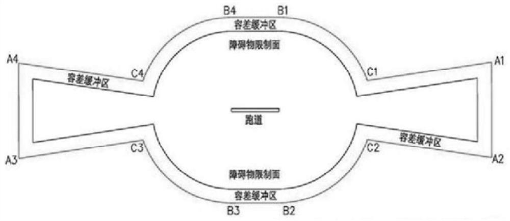
[0250] Such as Figure 6 Combined with the actual flight data of an airport in the past month, the specific implementation is as follows:

[0251] The characteristics of an airport are as follows:

[0252]The airport discussed is a single-runway airport, and the runway corresponds to an arrival procedure and a departure procedure, and the vicinity of the airport is flat;

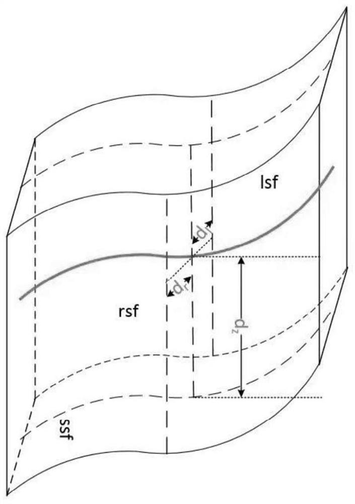
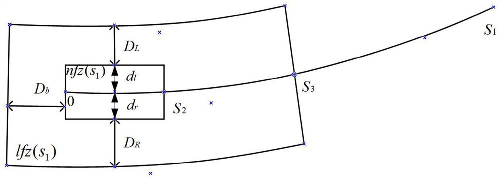
[0253] The parameter s corresponding to the arrival segment and the departure segment 1 Both are 10,000 meters, and the expression of the segment curve and the corresponding error distribution are known;

[0254] S1 Designate the core area of ​​the control area according to the collision risk probability e

[0255] The core area of ​​the control area is mainly based on the operational performance of the flight segment, and the operational data is established after risk assessment.

[0256] 1.1 Entry procedure

[0257] Without loss of generality, the flight is on the final approach segment is a straigh...


PUM


Abstract

The present invention provides a method for demarcating an airport UAV control area based on collision risk, comprising the following steps: S1 designate the inner core area of ​​the control area according to the collision risk probability e; S2 designate the corresponding core area based on the inner core area of ​​the control area The buffer zone of the control area; S3 defines the control area for drones, which is the union of the core area of ​​the control area and the buffer zone of the control area. The method provided by the present invention is the first domestic method of classifying and demarcating the flight area around the airport with UAVs as the object. Using this method, the core area of ​​the control area, the buffer area of ​​the control area, and the flyable area of ​​the UAV are delineated. Provide technical support for drone-related regulations. Ensure that the refined operation management of drones is realized without affecting the safety and efficiency of civil aviation aircraft operations.

Description

technical field [0001] The invention relates to the technical field of air traffic control, in particular to the air operation management of unmanned aerial vehicles. Background technique [0002] Unmanned aerial vehicle (UAV) is an aircraft managed by a control station (including remote control or autonomous flight), also known as remotely piloted aircraft. Due to the characteristics of good mobility, high survivability, and strong overload capacity, UAVs have broad application prospects in logistics transportation, power line inspection, agriculture, forestry and plant protection, emergency rescue and disaster relief, and geographic surveying and mapping. [0003] However, while the civilian UAV market has been expanding in recent years, due to the fact that UAVs are easy to manufacture, easy to obtain, and have a wide range of users, there are also various risks hidden in the operation of UAVs. Among them, the most typical The biggest risk is to interfere with the normal...

Claims


Application Information

Patent Timeline
Patent Type & Authority Patents(China)
IPC IPC(8): G05D1/10
CPCG05D1/101
Inventor 张建平邹翔谢方泉吴卿刚陈振玲
Owner THE SECOND RES INST OF CIVIL AVIATION ADMINISTRATION OF CHINA
Why Eureka
Try Eureka