Signal source synchronization detection method

A technology of synchronous detection and signal source, applied in the direction of image communication, television, electrical components, etc., can solve the problems of uncertainty, time inconsistency, etc.

Inactive Publication Date: 2020-05-15
北京仁光科技有限公司
View PDF6 Cites 4 Cited by
  • Summary
  • Abstract
  • Description
  • Claims
  • Application Information

AI Technical Summary

Problems solved by technology

[0003] However, when the original signal needs to be displayed on the 2x2 screen in the figure, the order of the various encoded parts sent by the encoder, network fluctuations, and differences in decoder performance all cause the decoder to receive the sa

Method used


Image

  • Signal source synchronization detection method
  • Signal source synchronization detection method
  • Signal source synchronization detection method

Examples


Embodiment Construction

[0018] The present invention will be exemplarily described below with reference to the accompanying drawings and embodiments. It should be noted that, in the case of no conflict, the embodiments in the present application and the features in the embodiments can be combined with each other. In addition, the described embodiments are some, not all, embodiments of the present invention.

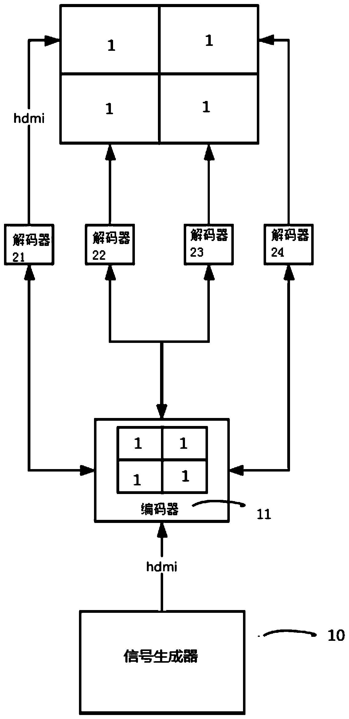
[0019] figure 1 A signal source synchronization detection system according to some embodiments of the present invention is shown, which can detect the synchronization of each part of the signal source in a distributed splicing display picture, and the signal source synchronization detection system includes: a signal generator 10, an encoder 11 and n decoders (21-24), n greater than 1.

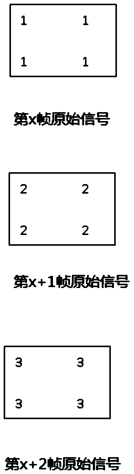
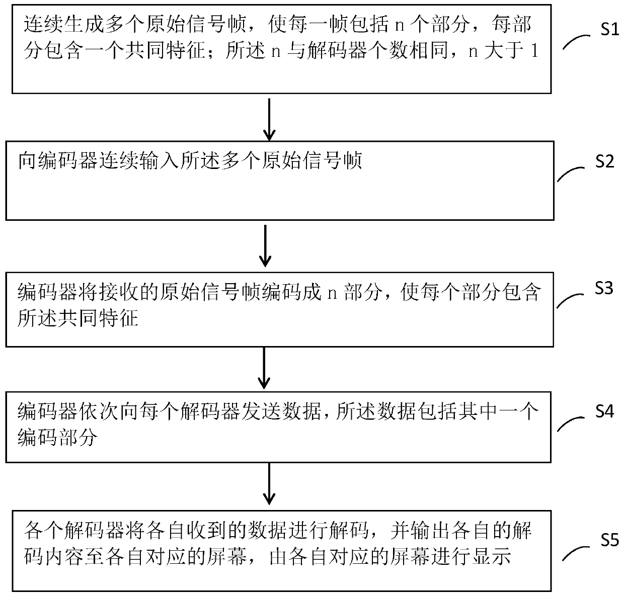
[0020] The signal generator 10 is used to continuously generate a plurality of original signal frames, so that each frame includes n parts, and each part contains a common feature, and continuously inputs the pl...


PUM


Abstract

The invention relates to a signal source synchronization detection method, which is used for detecting the synchronism of each part of a signal source in a distributed spliced display picture, and comprises the following steps of: continuously generating a plurality of original signal frames, so that each frame comprises n parts, and each part comprises a common characteristic; the number of the nbeing the same as that of the decoders, and n being greater than 1; continuously inputting the plurality of original signal frames into an encoder; encoding, by the encoder, a received original signal frame into n parts, so that each part comprises the common features; sequentially sending data to each decoder, wherein the data comprising one encoding part; and decoding the respective received data and outputting respective decoded content to the respective corresponding screen by each decoder, and displaying the respective decoded content by the respective corresponding screen. According tothe invention, the problem in synchronization detection for all parts of a signal source in the distributed spliced display picture in the prior art can be visually and effectively solved.

Description

technical field [0001] The invention relates to a signal source synchronization detection method and system, which are used for detecting the synchronization of each part of the signal source in a distributed splicing display screen. Background technique [0002] In the existing distributed mosaic display technology, such as figure 1 As shown, the encoder divides the original signal of frame x into 4 parts for encoding, that is, encodes into 4 parts, each part is sent to the corresponding decoder for decoding, and the decoded content is sent to each screen, each screen Stitched together to display the original signal of the entire xth frame. Depending on the number of decoders, the encoder can encode the original signal of the xth frame into a number of parts that are the same as the number of decoders. [0003] However, when the original signal needs to be displayed on the 2x2 screen in the figure, the order of the various encoded parts sent by the encoder, network fluctu...

Claims


Application Information

Patent Timeline
IPC IPC(8): H04N17/00
CPCH04N17/00
Inventor 谭登峰崔金其他发明人请求不公开姓名
Owner 北京仁光科技有限公司
Why Eureka
Try Eureka