Inertial reference space-time accurate alignment method of optical navigation sensor

An optical navigation and precise alignment technology, applied in the direction of instruments, measuring devices, etc., can solve the problems of impossible to obtain accurate star sensors and optical navigation sensor installation matrix

Active Publication Date: 2020-06-02
SHANGHAI AEROSPACE CONTROL TECH INST
View PDF9 Cites 2 Cited by
  • Summary
  • Abstract
  • Description
  • Claims
  • Application Information

AI Technical Summary

Problems solved by technology

[0003] The existing technology is to calculate the attitude quaternion of the Mars orbiter relative to the inertial system through the measurement quaternion of the star sensor, and then solve the optical navigation quaternion through the installation matrix of the optical navigation sensor relative to the Mars orbiter. The attitude quaternion of the sensor relative to the inertial system, this method needs to accurately know the attitude quaternion of the star sensor and the optical navigation sensor, however, it is impossible to obtain accurate The star sensor and the installation matrix of the optical navigation sensor
In addition, the exposure time of the attitude output by the star sensor and the exposure time measured by the optical navigation sensor cannot be completely synchronized. Therefore, it is necessary to study a precise alignment method of the inertial reference time and space of the optical navigation sensor to avoid external environmental factors and exposure time. Attitude and navigation errors due to jet lag

Method used


Image

  • Inertial reference space-time accurate alignment method of optical navigation sensor
  • Inertial reference space-time accurate alignment method of optical navigation sensor
  • Inertial reference space-time accurate alignment method of optical navigation sensor

Examples


Embodiment Construction

[0031] The present invention will be further elaborated below in conjunction with embodiment.

[0032] The invention provides an inertial reference space-time precise alignment method of an optical navigation sensor to avoid attitude and navigation errors caused by external environmental factors and exposure time differences.

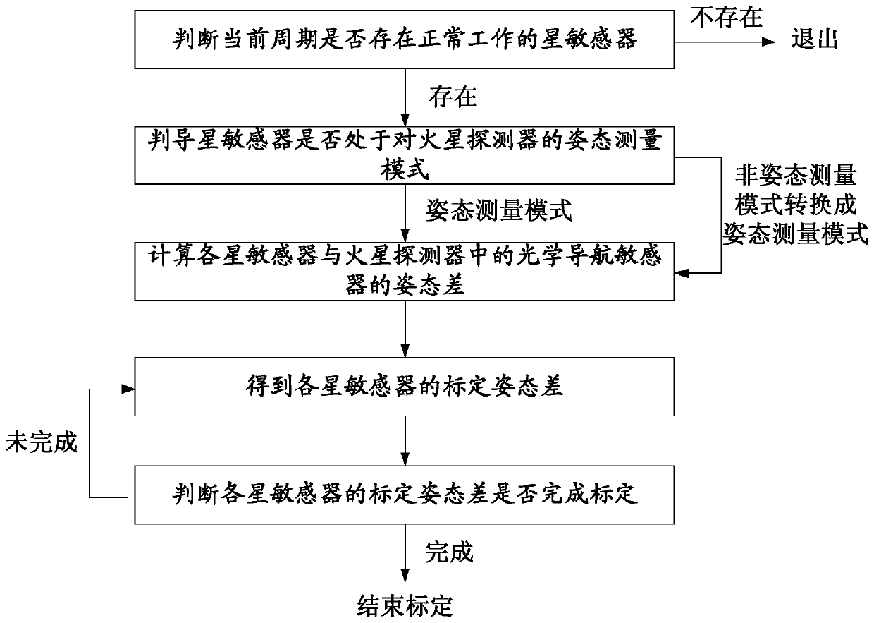
[0033] Such as figure 1 As shown, the inertial reference space-time precise alignment method mainly includes the following steps:

[0034] Step 1. Start the calibration process, and judge whether there is a normal working star sensor in the current period T; when there is a normal working star sensor, enter step 2; otherwise, exit the calibration process; the method for judging whether the star sensor is working normally is: When the star sensitivity reference modulus of the star sensor is 0.9-1.1, the star sensor is considered to be working normally; otherwise, the star sensor is considered to be working abnormally.

[0035] Step 2. Determine whether...


PUM


Abstract

The invention relates to an inertial reference space-time accurate alignment method of an optical navigation sensor, and belongs to the technical field of Mars surround optical navigation sensor inertial reference alignment. The method comprises the following steps: step 1, when a normally working star sensor exists, entering step 2; otherwise, exiting the calibration process; 2, when the star sensor is in an attitude measurement mode, entering a step 3; otherwise, switching to an attitude measurement mode, and entering the step 3; step 3, calculating an attitude difference xk between each star sensor and the optical navigation sensor, wherein k is the serial number of the star sensor; 4, obtaining a calibration attitude difference yk of each star sensor by adopting a calibration algorithm; step 5, when the calibration attitude difference yk of the star sensor completes calibration, ending the attitude difference calibration work of the star sensor and the optical navigation sensor; otherwise, continuing to perform attitude difference calibration on the star sensor. According to the invention, error sources such as installation measurement errors and thermal deformation errors areavoided, and the in-orbit alignment precision of the optical navigation sensor is improved.

Description

technical field [0001] The invention belongs to the technical field of inertial reference alignment of an optical navigation sensor of a Mars orbiter, and relates to an inertial reference time-space precise alignment method of an optical navigation sensor. Background technique [0002] During the process of optical autonomous navigation, the Mars orbiter needs to know the attitude transformation relationship of the optical navigation sensor relative to the inertial system to preprocess the navigation information. [0003] The existing technology is to calculate the attitude quaternion of the Mars orbiter relative to the inertial system through the measurement quaternion of the star sensor, and then solve the optical navigation quaternion through the installation matrix of the optical navigation sensor relative to the Mars orbiter. The attitude quaternion of the sensor relative to the inertial system, this method needs to accurately know the attitude quaternion of the star se...

Claims


Application Information

Patent Timeline
Patent Type & Authority Applications(China)
IPC IPC(8): G01C25/00
CPCG01C25/005
Inventor 张玉花肖东东操宏磊张超施桂国陈纾
Owner SHANGHAI AEROSPACE CONTROL TECH INST
Why Eureka
Try Eureka