
Demolding mechanism of air conditioner air inlet filter element cover injection mold

A technology of injection mold and demoulding mechanism, which is applied in household appliances, other household appliances, household components, etc., can solve the problems of large space occupation, poor reliability, unstable internal structure, etc., and achieves a space-saving and high reliability Effect

Inactive Publication Date: 2020-06-05
NINGBO FANGZHENG TOOL
View PDF1 Cites 0 Cited by
  • Summary
  • Abstract
  • Description
  • Claims
  • Application Information

AI Technical Summary

Problems solved by technology

[0002] The side of the air conditioner intake filter cover is provided with a protruding post protruding from the air conditioner intake filter cover, and the lower end of the protruding post is provided with a barb. The structure at this position has barbs because it is a functional area structure, as shown in Figure 5. According to the current situation With technology, there are two directions of barbs on the side of the product at the same time. It is necessary to design the slider + inclined top structure to form. According to the conventional method, the large slider will be made with a small slider, and the small slider will be equipped with a dovetail core-pulling structure, and a spring will be added inside to assist. The small slider ejects the mechanism, so the internal structure is unstable, the spring has fatigue strength, there is a risk of failure, and the reliability is poor. At the same time, the small slider and its dovetail groove are on the large slider, which takes up a lot of space and affects the performance of the large slider. strength

Method used


Image

  • Demolding mechanism of air conditioner air inlet filter element cover injection mold
  • Demolding mechanism of air conditioner air inlet filter element cover injection mold
  • Demolding mechanism of air conditioner air inlet filter element cover injection mold

Examples


Embodiment Construction

[0017] The present invention will be further described below in conjunction with the accompanying drawings and specific embodiments.

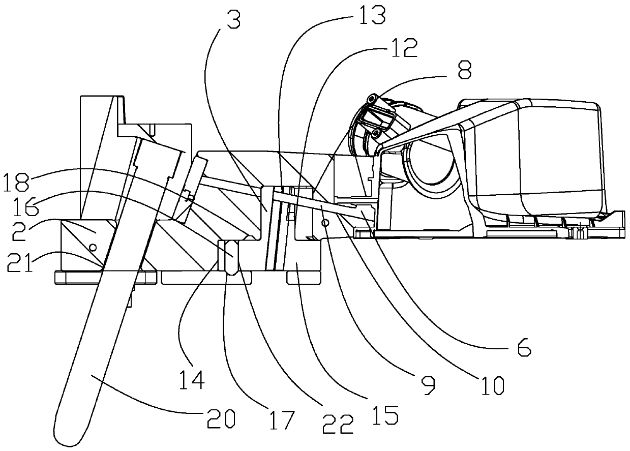
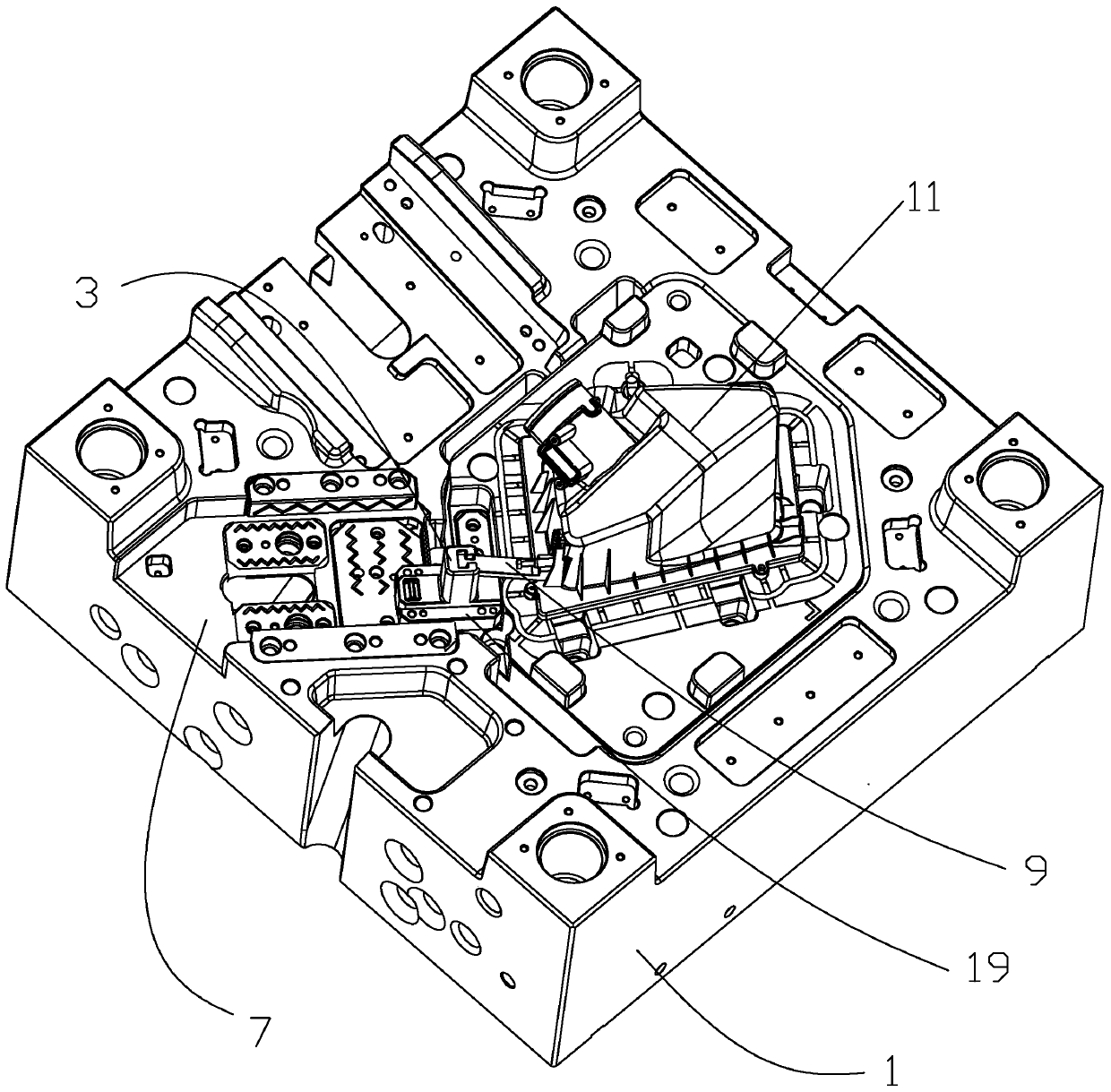
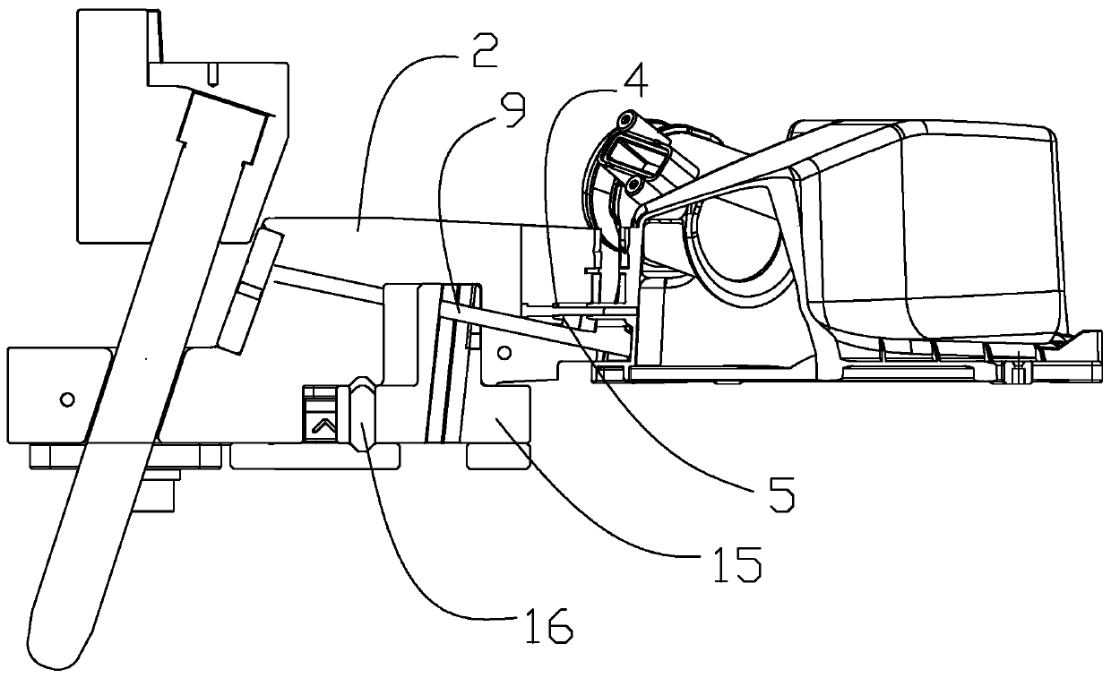
[0018] As shown in the figure, the present invention provides a demoulding mechanism for the injection mold of the air-conditioning air intake filter cover, which includes a lower mold 1 and a large slider 2 for molding the side of the product 11. The upper surface of the lower mold 1 is provided with a slide Slot 7, the large slider 2 is slidably fitted in the chute 7, it also includes a small slider seat 3, a pull rod 9 and a core-pulling inclined top 6 for forming the barb 5 in the boss 4, the described The bottom surface of the large slider 2 is provided with an open groove 8 with an opening downward, and the small slider seat 3 is located in the chute 7 and the small slider seat 3 can be slidably fitted in the open groove 8. The large slider 2 is provided with a passage 10, the passage 10 communicates with the open groove 8 and the barb 5,...


PUM


Abstract

The invention discloses a demolding mechanism of an air conditioner air inlet filter element cover injection mold. The demolding mechanism comprises a lower mold and a big slider for forming the sideface of the product. The upper surface of the lower mold is provided with a slide groove. The big slider is in sliding fit with the interior of the slide groove. The demolding mechanism further comprises a small slider base, a pull rod and an element pulling inclined top for forming a barb in a protruding column. The bottom surface of the big slider is provided with an opening groove with a downward opening. The small slider base is located in the slide groove and is in sliding fit with the interior of the opening groove. The big slider is internally provided with a channel. The channel communicates with the opening groove and the barb. One end of the pull rod is arranged at the upper end of the small slider base. The other end of the pull rod penetrates through the channel to be connectedwith the element pulling inclined top. The axis of the channel is perpendicular to the element pulling direction of the barb. A distance is formed between the small slider base and the opening groove. The demolding mechanism of the air conditioner air inlet filter element cover injection mold is high in reliability and small in occupied space.

Description

technical field [0001] The invention relates to the field of injection molds, in particular to a demoulding mechanism for an injection mold of an air-conditioning intake filter core cover. Background technique [0002] The side of the air conditioner intake filter cover is provided with a protruding post protruding from the air conditioner intake filter cover, and the lower end of the protruding post is provided with a barb. The structure at this position has barbs because it is a functional area structure, as shown in Figure 5. According to the current situation With technology, there are two directions of barbs on the side of the product at the same time. It is necessary to design the slider + inclined top structure to form. According to the conventional method, the large slider will be made with a small slider, and the small slider will be equipped with a dovetail core-pulling structure, and the spring will be added inside. The small slider ejects the mechanism, so the in...

Claims


Application Information

Patent Timeline
Patent Type & Authority Applications(China)
IPC IPC(8): B29C45/33B29L31/14
CPCB29C45/33B29C45/332B29L2031/14
Inventor 彭佩方永杰胡迪雷立波薛军建
Owner NINGBO FANGZHENG TOOL
Learn More